


Appendix
9.2.7
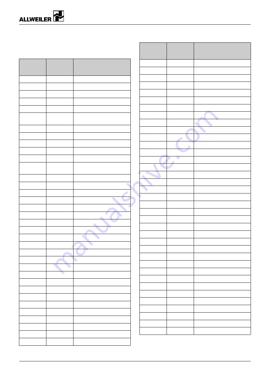
Height offset to align the motor using
adjusting screw
Height
adjustment
[mm]
Rotation
angle of
spindle [°]
Setting aid
0.02
5
–
0.04
10
–
0.06
15
–
0.08
20
–
0.10
25
–
0.13
30
Shaft key surface to point of
hexagon
0.15
35
–
0.17
40
–
0.19
45
–
0.21
50
–
0.23
55
–
0.25
60
Shaft key surface to shaft
key surface
0.27
65
–
0.29
70
–
0.31
75
–
0.33
80
–
0.35
85
–
0.38
90
1/4 turn
0.40
95
–
0.42
100
–
0.44
105
–
0.46
110
–
0.48
115
–
0.50
120
–
0.52
125
–
0.54
130
–
0.56
135
–
0.58
140
–
0.60
145
–
0.63
150
–
0.65
155
–
0.67
160
–
0.69
165
–
0.71
170
–
0.73
175
–
Height
adjustment
[mm]
Rotation
angle of
spindle [°]
Setting aid
0.75
180
1/2 turn
0.77
185
–
0.79
190
–
0.81
195
–
0.83
200
–
0.85
205
–
0.88
210
–
0.90
215
–
0.92
220
–
0.94
225
–
0.96
230
–
0.98
235
–
1.00
240
–
1.02
245
–
1.04
250
–
1.06
255
–
1.08
260
–
1.10
265
–
1.13
270
3/4 turn
1.15
275
–
1.17
280
–
1.19
285
–
1.21
290
–
1.23
295
–
1.25
300
–
1.27
305
–
1.29
310
–
1.31
315
–
1.33
320
–
1.35
325
–
1.38
330
–
1.40
335
–
1.42
340
–
1.44
345
–
1.46
350
–
1.48
355
–
1.50
360
1 revolution
Tab. 22
Height setting on the adjusting screw
160-276/0 – 550 406
BA-2017.02 en-US
CNH-ML series
43