508297-01
Page 51 of 57
Issue 2219
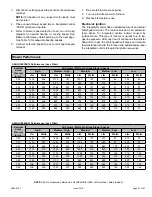
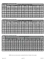
Blower Performance
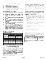
A96UH1E030B12 Performance (Less Filter)
External
Static
Pressure
in. w.c.
Air Volume / Watts at Various Blower Speeds
High
Medium - High
Medium
Medium - Low
Low
cfm
Watts
cfm
Watts
cfm
Watts
cfm
Watts
cfm
Watts
0.00
1435
346
1170
191
1000
127
775
62
705
45
0.10
1400
351
1130
199
955
132
735
71
635
48
0.20
1360
358
1085
207
905
137
680
81
515
50
0.30
1325
370
1055
217
865
148
625
84
445
55
0.40
1300
382
1020
227
815
157
570
91
380
61
0.50
1265
387
990
231
785
161
515
95
310
66
0.60
1235
402
945
244
735
168
475
104
265
68
0.70
1200
411
910
253
710
175
425
107
215
72
0.80
1160
420
885
260
660
183
355
114
175
75
A96UH1E045B12 Performance (Less Filter)
External
Static
Pressure
in. w.c.
Air Volume / Watts at Various Blower Speeds
High
Medium - High
Medium
Medium - Low
Low
cfm
Watts
cfm
Watts
cfm
Watts
cfm
Watts
cfm
Watts
0.00
1460
335
1285
235
1190
170
910
85
870
75
0.10
1430
350
1260
245
1155
185
885
95
830
85
0.20
1405
365
1235
255
1125
200
860
105
800
90
0.30
1375
370
1205
265
1090
210
825
115
755
95
0.40
1350
380
1175
275
1055
215
780
125
710
105
0.50
1315
385
1145
285
1020
230
735
130
665
115
0.60
1245
375
1110
295
980
240
685
140
620
125
0.70
N/A
N/A
1070
305
940
250
640
145
575
135
0.80
N/A
N/A
1020
310
905
260
600
155
530
140
NOTE
: All air is measured external to unit without filter (filter not furnished - field provided)
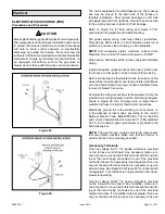
3. Disconnect existing speed tap at control board speed
terminal.
NOTE:
Termination of any unused motor leads must
be insulated.
4. Place unused blower speed tap on integrated control
“PARK” terminal or insulate.
5. Refer to blower speed selection chart on unit wiring
diagram for desired heating or cooling speed. See
Blower performance data beginning on the next page.
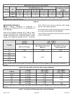
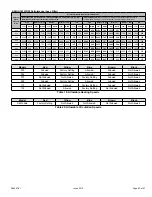
See Table 19 for allowable heating speeds.
6. Connect selected speed tap at control board speed
terminal.
7. Re-secure blower access panel.
8. Turn on electrical power to furnace.
9. Recheck temperature rise.
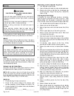
Electronic Ignition
The integrated control has an added feature of an internal
Watchguard control. The feature serves as an automatic
reset device for integrated control lockout caused by
ignition failure. This type of lockout is usually due to low
gas line pressure. After one hour of continuous thermostat
demand for heat, the Watchguard will break and remake
thermostat demand to the furnace and automatically reset
the integrated control to begin the ignition sequence.

