


508298-01
Page 13 of 55
Issue 2219
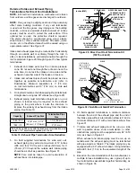
Pipe & Fittings Specifications
All pipe, fittings, primer and solvent cement must conform
with American National Standard Institute and the American
Society for Testing and Materials (ANSI/ASTM) standards.
The solvent shall be free flowing and contain no lumps,
undissolved particles or any foreign matter that adversely
affects the joint strength or chemical resistance of the
cement. The cement shall show no gelation, stratification,
or separation that cannot be removed by stirring. Refer to
Table 4 below for approved piping and fitting materials.
Solvent cements for plastic pipe are flammable liquids
and should be kept away from all sources of ignition.
Do not use excessive amounts of solvent cement when
making joints. Good ventilation should be maintained to
reduce fire hazard and to minimize breathing of solvent
vapors. Avoid contact of cement with skin and eyes.
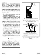
CAUTION
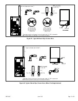
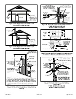
The exhaust and intake connections are made of PVC.
Use PVC primer and solvent cement when using PVC
vent pipe. When using ABS vent pipe, use transitional
solvent cement to make connections to the PVC fitting
in the unit.
IMPORTANT
Use PVC primer and solvent cement or ABS solvent
cement meeting ASTM specifications; refer to Table 4.
As an alternate, use all purpose cement, to bond ABS,
PVC, or CPVC pipe when using fittings and pipe made of
the same materials. Use transition solvent cement when
bonding ABS to either PVC or CPVC.
Low temperature solvent cement is recommended during
cooler weather. Metal or plastic strapping may be used as
vent pipe hangers. Uniformly apply a liberal coat of PVC
primer for PVC or use a clean dry cloth for ABS to clean
inside socket surface of fitting and male end of pipe to
depth of fitting socket.
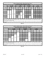
Capacity
Vent Pipe
Dia.
(in.)
Standard
Concentric
Flush Mount Kit
Wall Kit
Field
Fabricated
1-1/2 inch
2 inch
3 inch
51W11 (US)
51W12 (CA)
2 inch
3 inch
71M80 (US)
4
44W92
(CA)
69M29 (US)
4
44W92
(CA)
60L46 (US)
4
444W93
(CA)
22G44 (US)
4
30G28 (CA)
44J40 (US)
4
81J20 (CA)
045
1
1-1/2
3
YES
YES
1
YES
5
YES
2
YES
N/A
N/A
2
3
YES
YES
1
YES
5
YES
2
YES
2-1/2
3
YES
YES
1
YES
5
YES
2
YES
3
3
YES
YES
1
YES
5
YES
2
YES
070
1
1-1/2
3YES
YES
1
YES
5
YES
2
YES
2
3YES
YES
1
YES
5
YES
2
YES
2-1/2
3
YES
YES
1
YES
5
YES
2
YES
3
3
YES
YES
1
YES
5
YES
2
YES
090
2
3
YES
N/A
YES
5
YES
N/A
YES
YES
2-1/2
3
YES
YES
5
YES
YES
YES
3
3
YES
YES
5
YES
YES
YES
110
2
YES
YES
5
YES
YES
YES
2-1/2
YES
YES
5
YES
YES
YES
3
YES
YES
5
YES
YES
YES
NOTE - Standard Terminations do not include any vent pipe or elbows external to the structure. Any vent pipe or elbows external to the structure must be included in total
vent length calculations. See vent length tables.* Kits must be properly installed according to kit instructions.
1Requires field-provided outdoor 1-1/2” exhaust accelerator.
2Concentric kits 71M80 and 44W92 include 1-1/2” outdoor accelerator, when used with 045 and 070 input models. When using 1-1/2 in. piping, the pipe must transition to
2in. pipe when used with the concentrci kit.
3 Flush mount kits 51W11 and 51W12 includes 1-1/2 in. outdoor exhaust accelerator, required when used with 045, 070 and 090 input models. When using 1-1/2 in. piping,
the pipe must transition to 2in. pipe when used with the flush mount kit.
4 Termination kits 30G28, 44W92, 44W93 and 81J20 are certified to ULC S636 for use in Canada only.
5 See table 10 for vent accelerator requirements
6 2inch to 1-1/2 inch reducer required. must be fied required.
Table 5. Outdoor Termination Kits Usage
Summary of Contents for A96DF1E
Page 32: ...508298 01 Page 32 of 55 Issue 2219 Figure 50 Trap Drain Assembly Using 1 2 PVC or 3 4 PVC ...
Page 51: ...508298 01 Page 51 of 55 Issue 2219 Troubleshooting Heating Sequence of Operation ...
Page 52: ...508298 01 Page 52 of 55 Issue 2219 Troubleshooting Heating Sequence of Operation continued ...
Page 53: ...508298 01 Page 53 of 55 Issue 2219 Troubleshooting Cooling Sequence of Operation ...
Page 54: ...508298 01 Page 54 of 55 Issue 2219 Troubleshooting Continuous Fan Sequence of Operation ...