background image

Image data flow and controls order

13

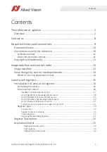
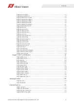
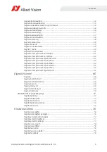
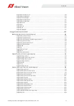
Goldeye Camera Link Register Controls Reference V1.0.0

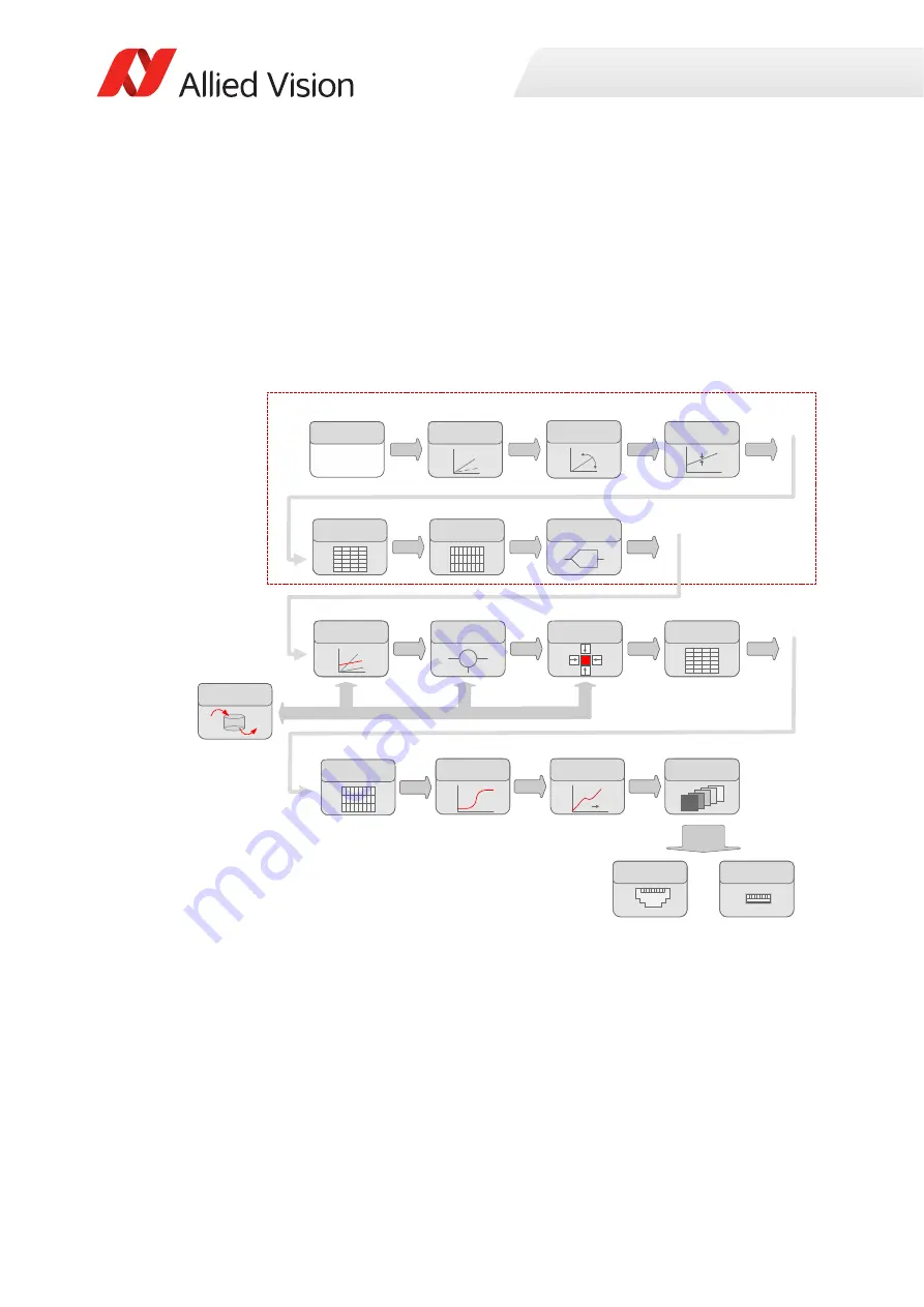
Image data flow 

To develop your application effectively, note the order in which the controls are
processed in Goldeye G/CL cameras.
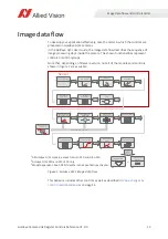
In the Goldeye G/CL User Guide, the image data flow describes the sequence of 
image processing steps inside the camera. The shown functionalities represent 
controls or control groups.

Note that, depending on firmware version, not all of the modules and controls 
shown in Figure 1 are available.   

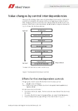
This behavior includes other controls as well as described in 

Value changes by 

control interdependencies

 on page 14.

Figure 1: Goldeye G/CL image data flow

Correc

Ɵ

on data 

memory

Correc

Ɵ

on data 

memory

Sensor

Sensor frontend

Sensor frontend

ADC

ADC

Analog

Analog

Analog

Analog

Black level

2

Black level

2

Gain

2

Gain

2

Sensor gain

1

Sensor gain

1

Sensor gain

1

n-bit

3

n-bit

3

Defect pixel 

correc

Ɵ

on (DPC)

Defect pixel 

correc

Ɵ

on (DPC)

Horizontal binning

Horizontal binning

Ver

Ɵ

cal Binning

Ver

Ɵ

cal Binning

Non uniformity 

correc

Ɵ

on (NUC)

Non uniformity 

correc

Ɵ

on (NUC)

Non uniformity 

correc

Ɵ

on (NUC)

Non uniformity 

correc

Ɵ

on (NUC)

n-bit

3

n-bit

3

n-bit

3

n-bit

3

Background 

correc

Ɵ

on

ɇ

+

-

Background 

correc

Ɵ

on

ɇ

+

-

n-bit

3

n-bit

3

n-bit

3

n-bit

3

n-bit

3

n-bit

3

n-bit

3

Camera Link 

interface

Camera Link 

interface

GigE interface

GigE interface

or

Camera Link 

interface

GigE interface

or

Auto contrast

Auto contrast

12     12

12     12

Look up table 

(LUT)

12     12

Look up table 

(LUT)

n-bit

3

n-bit

3

Frame memory

Frame memory

n-bit

3

n-bit

3

Horizontal 

decima

Ɵ

on

2

Horizontal 

decima

Ɵ

on

2

Ver

Ɵ

cal 

decima

Ɵ

on

2

Ver

Ɵ

cal 

decima

Ɵ

on

2

Analog

Analog

Correc

Ɵ

on data pipeline

1

 All Goldeye G/CL models, except for G/CL-030 and G/CL-130

2

 Goldeye G/CL-030 and G/CL-130 only

3

 Model dependent: See ADC bit depths in the Specifications chapter.

Summary of Contents for Goldeye

Page 1: ...CAMERA LINK SWIR CAMERAS Goldeye Camera Link Register Controls Reference V1 0 0 Allied Vision Technologies GmbH Taschenweg 2a 07646 Stadtroda Germany 2021 Nov 12...

Page 2: ...l release If you need further information on Goldeye CL register controls please visit www alliedvision com en about us contact us technical support repair rma Further information and feedback For mor...

Page 3: ...pendent controls 14 Camera Link registers 15 Introduction to Camera Link registers 16 Controlling the camera 16 Introduction to GenCP 16 ReadMem Command Packet Layout 17 GenCP ReadMem Acknowledge Pack...

Page 4: ...oMin 36 RegExposureAutoMax 37 RegExposureAutoTarget 37 RegExposureAutoRate 38 RegContrastAuto 38 RegContrastAutoInq 39 RegContrastAutoIntensityMax 39 RegContrastAutoIntensityMin 40 RegIntegrationMode...

Page 5: ...tActive 63 RegSensorTemperatureSetpointMode 63 RegSensorTemperatureSetpointSelector 64 RegSensorTemperatureSetpointValue 64 RegSensorTemperatureTargetSetpoint 65 DigitalIOControl 66 RegIoInq 66 RegLin...

Page 6: ...ode 91 RegBCInq 91 RegBCDatasetCount 92 RegBCState 92 RegBCIntegrationValid 93 DefectPixelCorrection subcategory 94 RegDPCDatasetActive 94 RegDPCDatasetActiveDescription 95 RegDPCDatasetDescription 95...

Page 7: ...egionY 113 RegMinHeight 113 RegHeightInc 114 RegMaxRegionY 114 RegPixelFormat 115 RegPixelFormatInq 116 RegSensorBits 117 RegSensorHeight 117 RegSensorType 117 RegSensorWidth 118 RegWidth 118 RegWidth...

Page 8: ...chenweg 2a 07646 Stadtroda Germany T 49 36428 677 0 Reception T 49 36428 677 230 Sales F 49 36428 677 28 Asia Pacific China Allied Vision Technologies Shanghai Co Ltd 2 2109 Hongwell Int Plaza 1602 Zh...

Page 9: ...Goldeye Camera Link Register Controls Reference V1 0 0 9 Document history and conventions This chapter includes Document history 10 Conventions used in this reference 10 Copyright and trademarks 11...

Page 10: ...emphasized to make them more visible Registers names Camera Link register names are displayed as mono spaced text Registers options Options for registers that are selectable by the user are displayed...

Page 11: ...ply endorsement Copyright 2021 Allied Vision GmbH All rights reserved Abbreviation Meaning R W Register is read or write R W Register is readable and it may be read or write depending on the user priv...

Page 12: ...Goldeye Camera Link Register Controls Reference V1 0 0 12 Image data flow and controls order This chapter includes Image data flow 13 Value changes by control interdependencies 14...

Page 13: ...Black level2 Black level2 Gain2 Gain2 Sensor gain1 Sensor gain1 Sensor gain1 n bit3 n bit3 Defect pixel correc on DPC Defect pixel correc on DPC Horizontal binning Horizontal binning Ver cal Binning V...

Page 14: ...ependent controls Changing one control s value affects other control s values such as If Height value is changed Then Other values may be affected such as for AcquisitionFrameRate and ExposureTime We...

Page 15: ...Goldeye Camera Link Register Controls Reference V1 0 0 15 Camera Link registers This chapter describes the registers for all Goldeye CL models...

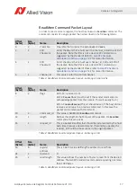
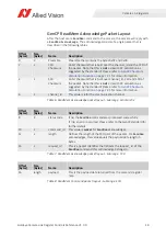
Page 16: ...ines the ReadMem command and the WriteMem command These commands are issued by the host and sent to the camera The camera decodes and processes them and returns an appropriate acknowledge packet Each...

Page 17: ...ommand packet layout Subrange Serial prefix Offset Bytes Size Bytes Name Description 8 2 flags Bit 0 13 reserved 0 Bit 14 RequestAck must be set if the sender commands an acknowledge packet from the c...

Page 18: ...lculation as suggested by the standard Please refer to GenCP Checksum Calculation Function on page 7 21 for more information 6 2 channel_id This value is 0 for the communication channel Table 6 ReadMe...

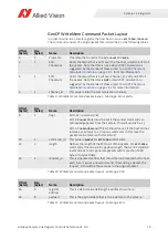
Page 19: ...em Command packet layout Subrange Serial prefix Offset Bytes Size Bytes Name Description 8 2 flags Bit 0 13 reserved 0 Bit 14 RequestAck must be set if the sender commands an acknowledge packet from t...

Page 20: ...GenCP Checksum Calculation Function on page 7 21 for more information 6 2 channel_id This value is 0 for the communication channel Table 12 WriteMem Acknowledge packet layout Subrange Serial prefix Of...

Page 21: ...nt32 nChecksum 0 uint16 nCurVal uint32 nByteCounter uint32 nNumBytesEven nNumBytes sizeof uint16 1 for reasons of performance this function is limited to 64Kb length Since the GenCP standard recommend...

Page 22: ...d flag set up to 3 times The Round Trip Time RTT for a command and acknowledge can be calculated by RTT Command Transfer Time Processing Time Acknowledge Transfer Time The Maximum Device Response Time...

Page 23: ...variants Inquiry registers allow the camera to inform about availability of functionalities These registers are usually several MaskedIntReg bit fields combined together under the same register addre...

Page 24: ...ic read and write operation is usually aligned to an IntReg of the size of 4 bytes The corresponding bit shifting and masking operations to read or write the MaskedIntReg need to be implemented by the...

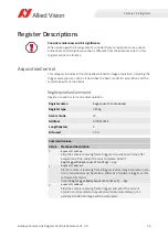
Page 25: ...s register controls reference Register name RegAcquisitionCommand Register type IntReg Access mode W Address 0x000130F4 Length Bytes 4 Bits used 31 0 Command values Value Name and description 0 Acquis...

Page 26: ...MaskedIntReg Access mode R Address 0x00013000 Length Bytes 4 Bits used 23 20 19 Bit assignment Bit Name and description 19 AcquisitionEnd If 1 AcquisitionEnd trigger is supported 20 AcquisitionStart I...

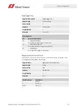
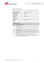
Page 27: ...n values Value Name and description 1 Continuous After an acquisition start event the camera will continuously receive frame trigger events See TriggerSelector and TriggerSource for more information 2...

Page 28: ...e with the camera Register name prefix RegAcquisitionModeInq Register type MaskedIntReg Access mode R Address 0x00013100 Length Bytes 4 Bits used 30 28 Bit assignment Bit Name and description 28 Multi...

Page 29: ...rent image region Register name RegAutoModeRegionHeight Register type IntReg Access mode R W Address 0x000140FC Length Bytes 4 Bits used 31 0 Units Pixels Possible values Description Camera dependent...

Page 30: ...t image region Register name RegAutoModeRegionOffsetY Register type IntReg Access mode R W Unit Pixels Address 0x000140F4 Length Bytes 4 Bits used 31 0 Possible values Description Camera dependent Def...

Page 31: ...dark end of the image histogram before calculating exposure adjustments Register name RegExposureAutoOutliersBright Register type IntReg Access mode R W Unit 0 01 Percent Address 0x000140EC Length By...

Page 32: ...Reg Access mode R W Address 0x00014104 Length Bytes 4 Bits used 31 0 Enumeration values Value Name and description 1 Off Automatic mode is off 2 Continuous Auto exposure runs always 3 Once Auto exposu...

Page 33: ...Bytes 4 Bits used 30 27 Bit assignment Bit Name and description 27 other Contains 1 if RegExposureAuto value other is supported 28 Once Contains 1 if RegExposureAuto value Once is supported 29 Contin...

Page 34: ...n currently set Register name RegExposureValueMax Register type IntReg Access mode R Unit Microseconds Address 0x0001410C Length Bytes 4 Bits used 31 0 Register name RegExposureValue Register type Int...

Page 35: ...AutoAdjustTol Register type IntReg Access mode R W Unit Percent Address 0x00014130 Length Bytes 4 Bits used 31 0 Possible values Description 5 Default Camera dependent Minimum Camera dependent Maximum...

Page 36: ...q Register type IntReg Access mode R W Address 0x00014114 Length Bytes 4 Bits used 31 30 Enumeration values Value Name and description 31 Mean Contains 1 if RegExposureAutoAlg value Mean is supported...

Page 37: ...if ExposureAutoAlg is Mean Register name RegExposureAutoMax Register type IntReg Access mode R W Address 0x00014120 Unit Microseconds Length Bytes 4 Bits used 31 0 Possible values Description Camera d...

Page 38: ...eg Access mode R W Unit Percent Address 0x00014128 Length Bytes 4 Bits used 31 0 Possible values Description 0 Default 1 Minimum slowest 100 Maximum fastest Register name RegContrastAuto Register type...

Page 39: ...0x00014180 Length Bytes 4 Bits used 31 29 Bit assignment Bit Name and description 31 Off Contains 1 if RegContrastAuto value Off is supported 30 WholeImage Contains 1 if RegContrastAuto value WholeIm...

Page 40: ...014188 Length Bytes 4 Bits used 31 0 Possible values Description 16383 Default 0 Minimum 16383 Maximum Attention Other bits at this address are used to control some internal camera settings and should...

Page 41: ...t multiple times in an array RegTriggerMode RegSoftwareTrigger RegTriggerSource RegTriggerEvent RegTriggerDelay The actual register address must for the corresponding trigger FrameStart The trigger th...

Page 42: ...tReg Access mode R W Address 0x00013418 for FrameStart trigger 0x000134D8 for AcquisitionStart trigger 0x00013518 for AcquisitionEnd trigger Length Bytes 4 Bits used 31 0 Enumeration values Value Name...

Page 43: ...trigger 0x000134D4 for AcquisitionStart trigger 0x00013514 for AcquisitionEnd trigger Length Bytes 4 Bits used 31 27 Bit assignment Bit Name and description 27 LevelLow If 1 camera supports triggerin...

Page 44: ...ighting source which will inherently have some fixed setup time Register name prefix RegTriggerInq Register type MaskedIntReg Access mode R Address 0x00013400 Length Bytes 4 Bits used 31 30 Bit assign...

Page 45: ...croseconds Address 0x00013164 Length Bytes 4 Bits used 31 0 Possible values Description None Default 0 Minimum Camera dependent Maximum If RegTriggerMode FrameStart Off and the FrameStart trigger is s...

Page 46: ...xedIntervalMax Longest fixed interval time possible the interval time must not exceed the value stored here Register name RegSoftwareTrigger Register type IntReg Access mode R W Address 0x00013160 Len...

Page 47: ...to FixedRate Other settings of the camera for example exposure time or bandwidth limitation may prevent this value from being applied exactly The camera will then try to get as close to the desired i...

Page 48: ...igger 0x000134D0 for AcquisitionStart trigger 0x00013510 for AcquisitionEnd trigger Length Bytes 4 Bits used 31 16 Enumeration values Value Name and description 0 Freerun Default Camera runs at maximu...

Page 49: ...End trigger Length Bytes 4 Bits used 31 25 Bit assignment Bit Name and description 21 Software Contains 1 if software trigger is supported 22 FixedRate Contains 1 if the camera can run without externa...

Page 50: ...ies RegSensorGain Sets the FPA gain level Register name RegSensorGain Register type IntReg Access mode R W Address 0x000B0094 Length Bytes 4 Bits used 31 0 Enumeration values Value Name and descriptio...

Page 51: ...are supported by the camera Register name RegFPAInqGainX Register type MaskedIntReg Access mode R Address 0x000B00AC Length Bytes 4 Bits used 31 29 Bit assignment Bit Name and description 29 Gain2 Co...

Page 52: ...dentifier of the product family of the device RegDeviceFirmwareVersion Firmware version of the device Register name RegDeviceReset Register type IntReg Access mode W Address 0x0000F318 Length Bytes 4...

Page 53: ...egister Controls Reference V1 0 0 RegHeartbeatTimeoutMS Controls the current heartbeat timeout of the link Register name RegHeartbeatTimeoutMs Register type IntReg Access mode R W Unit Milliseconds Ad...

Page 54: ...0 Bit assignment Bit Name and description 0 Baud9600 If 1 serial port runs at 9 600 bits per second 1 Baud19200 If 1 serial port runs at 19 200 bits per second 2 Baud38400 If 1 serial port runs at 38...

Page 55: ...nd description 0 Baud9600 If 1 serial port can run at 9 600 bits per second 1 Baud19200 If 1 serial port can run at 19 200 bits per second 2 Baud38400 If 1 serial port can run at 38 400 bits per secon...

Page 56: ...nd flags of the camera Example entry Goldeye G 008 4068080 RegDeviceModelName Camera family and model name such as Goldeye CL 032 Software should use the DevicePartNumber to distinguish between models...

Page 57: ...ddress 0x00024004 for RelativeHumiditySensor 0x00024008 for RelativeHumiditySensorBoard 0x0002400C for RelativeHumidityMainBoard Length Bytes 4 Bits used 31 0 Register name prefix RegStatusRelativeHum...

Page 58: ...selected by DeviceTemperatureSelector Register name RegDeviceSerialNumber Register type StringReg Access mode R Address 0x00000144 Length Bytes 64 Register name RegTemperature Register type Array of F...

Page 59: ...refix RegTemperatureInq Register type MaskedIntReg Access mode R Address 0x00024100 Length Bytes 4 Bits used 31 29 Bit assignment Bit Name and description 29 MainBoard Contains 1 if a temperature sens...

Page 60: ...Reg Access mode R Address 0x00000004 Length Bytes 64 Register name RegTIDC_Mode Register type MaskedIntReg Access mode R W Address 0x000B00BC Length Bytes 4 Bits used 31 0 Bit assignment Bit Name and...

Page 61: ...Bytes 4 Bits used 31 0 Register name RegSensorTemperatureControlMode Register type IntReg Access mode R W Address 0x000B0004 Length Bytes 4 Default TemperatureControl Bits used 31 0 Enumeration values...

Page 62: ...ength Bytes 4 Bits used 31 0 Enumeration values Value Name and description 0 Off Sensor cooling is off 1 Deviated Sensor temperature deviates from the setpoint value 2 Stable Sensor temperature is sta...

Page 63: ...ster type IntReg Access mode R Address 0x000B0164 Length Bytes 4 Bits used 31 0 Register name RegSensorTemperatureSetpointMode Register type IntReg Access mode R W Address 0x000B005C Length Bytes 4 De...

Page 64: ...egSensorTemperatureSetpointValue The setpoint temperature corresponding to the setpoint selected by RegSensorTemperatureSetpointSelector Register name RegSensorTemperatureSetpointSelector Register typ...

Page 65: ...ities if RegSensorTemperatureControlMode is set to TemperatureControlTarget The selected setpoint is automatically activated Decrementing to Setpoints lower than TargetSetpoint by SetpointMode Auto is...

Page 66: ...ntains 1 if Strobe1 is supported 20 LineOut4 Contains 1 if LineOut4 line is supported 21 LineOut3 Contains 1 if LineOut3 line is supported 22 LineOut2 Contains 1 if LineOut2 line is supported 23 LineO...

Page 67: ...neInGlitchFilter value causes a latency of FrameTrigger by the same amount Register name RegLineInGlitchFilter Register type Array of IntReg Access mode R W Unit Nanoseconds Addresses 0x000151D0 for L...

Page 68: ...ss mode R Unit Nanoseconds Address 0x000151C0 Length Bytes 4 Bits used 31 0 Register name RegLineInLevels Register type IntReg Access mode R Address 0x00015110 Length Bytes 4 Bits used 31 24 Bit assig...

Page 69: ...ineOutPolarity also affects the related digital output line when it is configured to GPO mode Register name RegLineOutLevels Register type IntReg Access mode R W Address 0x00015114 Length Bytes 4 Bits...

Page 70: ...0 GPO General purpose output 1 AcquisitionTriggerReady Active once the camera has been recognized by the host computer and is ready to start acquisition 2 FrameTriggerReady Active when the camera is i...

Page 71: ...y Active when there is an external trigger at CC2 14 CC3 Camera Link models only Active when there is an external trigger at CC3 15 CC4 Camera Link models only Active when there is an external trigger...

Page 72: ...a source signal which can be useful for example when trying to synchronize a camera exposure to an external signal RegStrobe1Delay Delay from strobe trigger to strobe output Display name StrobeContro...

Page 73: ...RegStrobeDelayMax Register type IntReg Access mode R Unit Microseconds Address 0x00015160 Length Bytes 4 Bits used 31 0 Possible values Description None Default 0 Minimum Camera dependent Maximum Regi...

Page 74: ...he strobe timing unit Register name RegStrobe1DurationMode Register type MaskedIntReg Access mode R W Address 0x00015174 Length Bytes 4 Bits used 0 Enumeration values Value Name and description 0 Sour...

Page 75: ...s been recognized by the host computer and is ready to start acquisition 2 FrameTriggerReady Active when the camera is in a state that will accept the next frame trigger 3 FrameTrigger Active when an...

Page 76: ...diate access buffer that allows the exchange of data between the camera file storage and the application RegFileAccessBufferSizeInBytes Represents the size of the FileAccessBuffer Register name RegFil...

Page 77: ...FreeBlocks Represents the number of free blocks in the file system Register name RegFileSystemBlockSizeInBytes Register type IntReg Access mode R Unit Bytes Address 0x000F0088 Length Bytes 4 Bits used...

Page 78: ...tion Represents the description of the file selected by FileSelector A maximum of 32 characters is allowed including the trailing null character Register name RegFileAccessLength Register type IntReg...

Page 79: ...ng the trailing null character RegFileOpenMode Selects the access mode in which a file is opened in the device Register name RegFileDescriptionBuffer Register type StringReg Access mode R Address 0x00...

Page 80: ...urned RegFileAttributeBuffer Contains the attribute that is to be used for newly created files or when the attribute of an existing file is changed Register name RegFileOperationExecute Register type...

Page 81: ...e this operation can be executed The data is read from the file position defined by FileAccessOffset and it is stored in the FileAccessBuffer 3 Write Writes FileAccessLength bytes from the FileAccessB...

Page 82: ...Shows the status of file operation execution Register name RegFileOperationStatus Register type IntReg Access mode R Address 0x000F0010 Length Bytes 4 Bits used 31 0 Enumeration values Value Name and...

Page 83: ...ial purposes Those file names cannot be used Therefore use only the file slots named below Using different file names may render the camera unusable Register name RegFileSelector Register type IntReg...

Page 84: ...31 0 Bit assignment Bit Name and description 31 RegIsFileSystemReady Contains 1 if the file system is ready to use 30 RegDoesFileExist Contains 1 if the currently selected file exists 29 RegIsFileOpe...

Page 85: ...ChangeFileAttribute Contains 1 if the attribute of the currently selected file can be changed Register name RegFileType Register type IntReg Access mode R Address 0x000F0024 Length Bytes 4 Bits used 3...

Page 86: ...o operating the image processing chain BackgroundCorrection subcategory The background correction is used as an additional correction based on actual operating conditions to optimize the result of the...

Page 87: ...era supports independent of the active output pixel format The offset value is added after subtraction of the correction image If set to the mean value of the correction image the background correctio...

Page 88: ...tion will wait after BCIntegrationStart until BCIntegrationFrameCount frames have been produced by the camera Frame triggering is not in the background correction domain This is controlled by function...

Page 89: ...ess mode W Address 0x000904B8 Length Bytes 4 Enumeration values Value Name and description 1 BCIntegrationStart Start the integration of BCIntegrationFrameCount frames depending on BCIntegrationMode N...

Page 90: ...Default Integrate Bits used 31 30 Enumeration values Value Name and description 0 Integrate After BCIntegrationStart a correction image that is the mean of BCIntegrationFrameCount images will be acqu...

Page 91: ...0400 Length Bytes 4 Bits used 31 28 Enumeration values Value Name and description 0 Off Image data is passed through unchanged 1 On Uses a previously integrated reference image for subtraction 2 Offse...

Page 92: ...ister type IntReg Access mode R Address 0x00090408 Length Bytes 4 Bits used 31 0 Register name RegBCState Register type IntReg Access mode R Address 0x000904BC Length Bytes 4 Bits used 31 0 Enumeratio...

Page 93: ...o the background correction can be applied Register name RegBCIntegrationValid Register type IntReg Access mode R Address 0x000904C0 Length Bytes 4 Bits used 31 0 Enumeration values Value Name and des...

Page 94: ...0 Writing to this register changes the active data set meaning it activates the data set indexed The maximum value allowed depends on the number of valid data sets in the camera and is reported by Reg...

Page 95: ...he maximum possible value of DPCDatasetSelector depends on the number of valid data sets in the camera The mapping of an index value to a specific correction data file may vary from camera to camera o...

Page 96: ...0200 Length Bytes 4 Bits used 31 28 Enumeration values Value Name and description 0 Off Image data is passed through unchanged 1 On Defects are replaced by a value calculated from surrounding non defe...

Page 97: ...PCDatasetCount The number of available DPC datasets in the camera Register name RegDPCDatasetCount Register type IntReg Access mode R Address 0x00090208 Length Bytes 4 Bits used 31 0 Default Camera de...

Page 98: ...s register changes the active data set meaning it activates the data set indexed The maximum value allowed depends on the number of valid data sets in the camera and is reported by RegNUCDatasetCount...

Page 99: ...e actual exposure time setting corresponds to the reference value This text is intended for informational purposes in the user interface display only For the actual values refer to NUCDatasetActiveExp...

Page 100: ...cted so that the actual sensor gain setting corresponds to the reference value The number of distinct reference values is limited by available correction data depending on the camera model Register na...

Page 101: ...eference values is limited by available correction data depending on the camera model Register name RegNUCDatasetActiveTemperature Register type FloatReg Access mode R Address 0x00090014 Length Bytes...

Page 102: ...me at acquisition of the data set indexed by RegNUCDatasetSelector The data set should be selected so that the actual exposure time setting corresponds to the reference value Register name RegNUCDatas...

Page 103: ...that the actual sensor gain setting corresponds to the reference value The number of distinct reference values is limited by available correction data depending on the camera model Register name RegNU...

Page 104: ...valid data points in the data set RegNUCDatasetNodeCount Number of nodes stored in the current NUC data set Register name RegNUCDatasetNodeSelector Register type IntReg Access mode R W Address 0x0009...

Page 105: ...setSelector Selects a data set for access The maximum possible value depends on the number of valid data sets in the camera The mapping of an index value to a specific correction data file may vary fr...

Page 106: ...ay be available The number of distinct reference values is limited by available correction data depending on the camera model Register name RegFloatRegNUCDatasetTemperature Register type FloatReg Acce...

Page 107: ...q Register type MaskedIntReg Access mode R Address 0x00090000 Length Bytes 4 Bits used 0 Enumeration values Value Name and description 0 The camera does not support non uniformity correction functiona...

Page 108: ...e whether the camera supports horizontal binning or vertical binning respectively Binning is the summing of charge or gray value of adjacent pixels on the sensor This generates a lower resolution imag...

Page 109: ...nd vertical binning can be adjusted separately RegBinningXMax Maximum supported horizontal binning value Register name RegBinningXValue Register type IntReg Access mode R W Address 0x00011108 Length B...

Page 110: ...and vertical binning can be adjusted separately RegBinningYMax Maximum supported vertical binning value Register name RegBinningYValue Register type IntReg Access mode R W Address 0x00011128 Length By...

Page 111: ...Register name RegHeight Register type IntReg Access mode R W Address 0x00012128 Length Bytes 4 Bits used 31 0 Possible values Description Camera dependent Default Camera dependent Minimum Maximum Tabl...

Page 112: ...idthInc Reports the AOI width granularity Register name RegRegionX Register type IntReg Access mode R W Address 0x0001212C Length Bytes 4 Bits used 31 0 Possible values Description 0 Default 0 Minimum...

Page 113: ...inHeight Minimum supported AOI height Register name RegMaxRegionX Register type IntReg Access mode R Address 0x0001214C Length Bytes 4 Bits used 31 0 Register name RegRegionY Register type IntReg Acce...

Page 114: ...AOI height granularity RegMaxRegionY Maximum AOI y axis start position Register name RegHeightInc Register type IntReg Access mode R Address 0x00012148 Length Bytes 4 Bits used 31 0 Register name RegM...

Page 115: ...ldeye G CL Technical Manuals for details Register name RegPixelFormat Register type IntReg Access mode R W Address 0x00012120 Length Bytes 4 Bits used 31 0 Enumeration values Value Name and descriptio...

Page 116: ...ntReg Access mode R Address 0x00012100 Length Bytes 4 Bits used 31 0 Bit assignment Bit Name and description 26 Mono12 If 1 camera supports Mono12 pixel format 30 Mono8 If 1 camera supports Mono8 pixe...

Page 117: ...Register name RegSensorBits Register type MaskedIntReg Access mode R Address 0x00011020 Length Bytes 4 Used Bits 23 16 Register name RegSensorHeight Register type IntReg Access mode R C Address 0x0001...

Page 118: ...g for example will change this value Register name RegSensorWidth Register type IntReg Access mode R Address 0x00011024 Length Bytes 4 Bits used 31 0 Register name RegWidth Register type IntReg Access...

Page 119: ...ncy Allows to change the clock frequency of the Camera Link backend Higher values allow higher bandwidths lower values reduce bit error problems with longer cables Register name RegClClockFrequency Re...

Page 120: ...reasing delay between recorded image and output image if configured inappropriately Register name RegClLValToFValDelay Register type IntReg Access mode R W Address 0x000C0014 Length Bytes 4 Bits used...

Page 121: ...s may impact the Camera Link timing with side effects such as image jitter output or increasing delay between image acquisition and output Register name RegClMinFValToFValDelay Register type IntReg Ac...

Page 122: ...size of image block payload Register name RegDeviceTapGeometry Register type MaskedIntReg Access mode R Address 0x0001211C Length Bytes 4 Used Bits 31 0 Enumeration values Value Name and description 1...

Page 123: ...mode R W Address 0x0001710C Length Bytes 4 Bits used 31 0 Enumeration values Value Name and description 0 Default Selects factory defaults to be loaded upon camera startup 1 UserSet1 Selects UserSet1...

Page 124: ...gister type IntReg Access mode W Address 0x00017108 Length Bytes 4 Bits used 31 0 Enumeration values Value Name and description 1 UserSetLoad Loads camera parameters from the user set specified by Reg...

Page 125: ...n the next user set load operation The factory defaults cannot be written using a user set write operation 1 UserSet1 Selects UserSet1 to be loaded or saved upon the next user set load save operation...

Page 126: ...uding the factory settings RegUserSetInq Register name RegUserSetCount Register type IntReg Access mode R Address 0x00017100 Length Bytes 4 Bits used 31 0 Register name RegUserSetInq Register type Mas...

Page 127: ...groundCorrection subcategory 86 C CC1 RegIoInqCC1 66 RegSyncInLevels 68 RegSyncOutSource 71 CC2 RegIoInqCC2 66 RegSyncInLevels 68 RegSyncOutSource 71 CC3 RegIoInqCC3 66 RegSyncInLevels 68 RegSyncOutSo...

Page 128: ...ImageCorrectionControl category 86 ImageFormatControl category 108 Imaging RegSyncOutSource 70 L LineIn1 RegIoInqLineIn1 66 RegLineInLevels 68 RegLineOutSource 70 LineIn2 RegIoInqLine2 66 RegLineInLe...

Page 129: ...0 RegBCIntegrationStart 88 RegBCIntegrationValid 93 RegBCMode 91 RegBCState 92 RegBinningXMax 109 RegBinningXValue 109 RegBinningYMax 110 RegBinningYValue 110 RegClClockFrequency 119 RegClLValToFValDe...

Page 130: ...34 RegExposureValueMin 33 RegFileAccessBuffer 76 RegFileAccessBufferSizeInBytes 76 RegFileAccessOffset 78 RegFileAttributeBuffer 80 RegFileDescription 78 RegFileDescriptionBuffer 79 RegFileOpenMode 79...

Page 131: ...68 RegLineInLevels 68 RegLineOutLevels 69 RegLineOutPolarity 69 RegLineOutSource 70 RegMaxRegionX 113 RegMaxRegionY 114 RegMinHeight 113 RegMinWidth 112 RegNUCDatasetActive 98 RegNUCDatasetActiveDesc...

Page 132: ...TemperatureSetpointActive 63 RegSensorTemperatureSetpointMode 63 RegSensorTemperatureSetpointSelector 64 RegSensorTemperatureSetpointValue 64 RegSensorTemperatureTargetSetpoint 65 RegSensorType 117 Re...

Page 133: ...rSourceInqSoftware 49 RegUserSetCmdExecute 124 RegUserSetCount 126 RegUserSetDefault 123 RegUserSetInq 126 RegUserSetNumber 124 125 RegWidth 118 RegWidthInc 112 RegWidthMax 118 S Strobe1 RegIoInqStrob...

Reviews:

Related manuals for Goldeye