background image

Preparing Cameras without

Sensor Cover Glass

Page 13 of 18

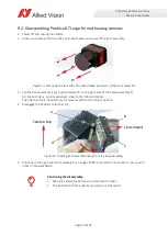
1. Place the camera on your work bench, with the sensor side facing up.
2. Place the magnifying glass above the camera, with sufficient space to access the TCG and the adhesive 

tapes with tools.

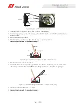
3. Take the spatula with one hand.
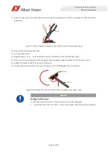
4. With the spatula, push the cover glass down to keep the sensor protected. 

Keep pushing down with the spatula until step 

15.

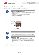
5. Take the screwdriver with the other hand.
6.  On the left side of the sensor, carefully push the tool tip of the screwdriver against the corner of the 

adhesive tape until it starts to come off. Continue lifting up the corner, until pliers can get a grip.

7. Put the screwdriver aside and take the pliers.
8.

Keep pushing down with the spatula until step 

15.

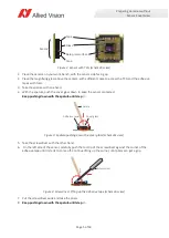
 Figure 19: Sensor with TCG (schematic view)

 Figure 20: Spatula pushing down the cover glass (schematic view)

 Figure 21: Screwdriver lifting up the adhesive tape (schematic view)

Sensor

Tape

Bare pixel surface

Glass

Tape

Mount

Mount

Cover glass

Adhesive tape

Spatula

Screwdriver

Summary of Contents for Alvium

Page 1: ...ing Wear ESD protective clothing Keep components away from your body and clothing Even if you are wearing a wrist strap your body is grounded but your clothes are not 3 2 Sensor damage Follow the inst...

Page 2: ...ewer shows a camera image of a moving shadow This proves proper camera function 4 Continue with the corresponding instructions 6 Instructions for housed Alvium cameras RCG on page 3 7 Instructions for...

Page 3: ...ver glass has been removed Therefore Alvium RCG cameras are calibrated for proper focus before shipping NOTICE Damage to the camera electronics and sensor Work in a dust free environment class 100 or...

Page 4: ...ing the sensor or the back lens use lenses with a maximum protrusion within camera specifications For details see your camera s user guide About the following instructions The instructions consist of...

Page 5: ...5 Take the screwdriver with the other hand 6 On the left side of the sensor carefully push the tool tip of the screwdriver against the corner of the adhesive tape until it starts to come off Continue...

Page 6: ...ng the spatula against the cover glass take the camera into the other hand 14 Rotate the camera with the sensor facing down 15 Slowly release the spatula from the cover glass until it disengages from...

Page 7: ...glass has been removed Therefore Manta RCG cameras are calibrated for proper focus before shipping NOTICE Damage to the camera electronics and sensor Work in a dust free environment class 100 or bette...

Page 8: ...nd unplug the camera 2 With a water resistant ink pen draw a line a across the joint between front assembly and body assembly This will serve as an index to reassemble the camera in correct orientatio...

Page 9: ...ping screws h in place remove the sensor unit i from the lens mount k Continue with 9 3 Removing the taped cover glass on page 12 Figure 10 Front assembly overview sensor unit and lens mount NOTICE Da...

Page 10: ...to the ribbon cable a The ribbon cable is included only for cameras with certain mount options 4 Disengage the flexible contact bar b 5 Continue to flip open the front assembly to an angle of 180 and...

Page 11: ...a line i across the center top of sensor unit and front assembly 8 Remove the sensor unit h from the lens mount k Continuing the disassembly Keep the camera flipped open as described in step 5 The ill...

Page 12: ...mera includes sensor units of Prosilica GT cameras Required tools Before you can remove the TCG please obtain the required tools shown below Required tools Tools short names Purpose Base magnifier or...

Page 13: ...the screwdriver with the other hand 6 On the left side of the sensor carefully push the tool tip of the screwdriver against the corner of the adhesive tape until it starts to come off Continue lifting...

Page 14: ...ly release the spatula from the cover glass until it drops out of the lens mount 16 Continue with 9 4 Reassembling Prosilica GT Extended Format housing cameras on page 15 for Prosilica GT Extended For...

Page 15: ...um torque of 4 lbf in 0 45 Nm 4 Position front assembly and body assembly so that markers g align 5 Mount the front assembly f to the body assembly h 6 Insert and tighten the four M2 x 8 socket head c...

Page 16: ...rews and spacers d and tighten screws at a maximum torque of 3 5 lbf in 0 4 Nm 4 Flip the front assembly g back to the body assembly h to approximately 45 5 Engage the flexible contact bar f to the ma...

Page 17: ...user guide Figure 31 Inserting the four M2 x 10 socket head cap screws of the front assembly NOTICE Damage to the sensor If you want to use your camera without lens observe 3 Safety notes on page 1 NO...

Page 18: ...avt distributors Support www alliedvision com en support www alliedvision com en about us contact us technical support repair rma Offices Europe Middle East and Africa Headquarters Allied Vision Techn...

Reviews: