background image

AT-x230-10GT, AT-x230-10GP, AT-x230-18GT, AT-x230-18GP, AT-x230-28GT and AT-x230-28GP Switch Installation Guide

67

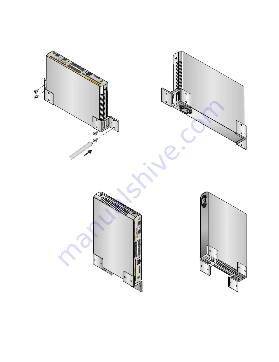
F

IGURE

 40. S

ECURING


THE

 AT-

X

230-10GT 

SWITCH


TO


THE


WALL


WITH


THE


FRONT


PANEL


FACING


UP

F

IGURE

 41. S

ECURING


THE

 AT-

X

230-10GT 

SWITCH


TO


THE


WALL


WITH


THE


FRONT


PANEL


FACING


RIGHT

3. Slide the switch between the brackets so that it rests against the 

bracket, as shown in the figures above.

4. Go to “Cabling the switch” on page 70.

Bracket position, viewed from above:

Bracket position, viewed from below:

Bracket position, 
viewed from below:

Bracket position, 
viewed from above:

Summary of Contents for AT-x230-10GP

Page 1: ...C613 04068 00 REV J AT x230 10GP AT x230 10GT AT x230 18GP AT x230 18GT AT x230 28GP AT x230 28GT Gigabit Ethernet Switches Installation Guide...

Page 2: ...espective owners Allied Telesis Inc reserves the right to make changes in specifications and other information contained in this document without prior written notice The information provided herein i...

Page 3: ...nt generates uses and can radiate radio frequency energy and if not installed and used in accordance with this instruction manual may cause harmful interference to radio communications Operation of th...

Page 4: ...Safety Statements Important The indicates that a translation of the safety statement is available in a PDF document titled Translated Safety Statements posted on the Allied Telesis website at www alli...

Page 5: ...on the AT x230 18GT Switch 19 Front and back panels on the AT x230 28GP Switch 21 Front and back panels on the AT x230 28GT Switch 23 Management software 25 Twisted pair ports 26 Cable requirements f...

Page 6: ...28GP switch in an equipment rack 64 Installing an AT x230 10GT switch on a wall 66 Installing an x230 18GT x230 28GT or x230 GP Series switch on a wall 68 Cabling the switch 70 Powering on the switch...

Page 7: ...mounting 57 Figure 29 Attaching cable tray brackets 58 Figure 30 Mounting an AT x230 10GT Switch in the brackets 58 Figure 31 Mounting an AT x230 10GT Switch in the rack 59 Figure 32 Securing cables t...

Page 8: ...from an SFP slot 79 Figure 51 Inserting an SFP transceiver into an SFP slot 80 Figure 52 Positioning the SFP handle in the upright position 80 Figure 53 Ejecting an SFP transceiver after lowering the...

Page 9: ...and PoE LED descriptions 36 Table 8 Link Activity Speed and Duplex Collision LED descriptions 38 Table 9 SFP Link Activity LED functional descriptions 40 Table 10 SD card LED functional descriptions...

Page 10: ...viii...

Page 11: ...Preface This guide contains the installation instructions for the following switches AT x230 10GP AT x230 10GT AT x230 18GP AT x230 18GT AT x230 28GP AT x230 28GT This preface contains the following s...

Page 12: ...ions inform you that performing or omitting a specific action may result in equipment damage or loss of data Warning Warnings inform you that performing or omitting a specific action may result in bod...

Page 13: ...tickets learn about RMAs and contact Allied Telesis technical experts USA and EMEA phone support Select the phone number that best fits your location and customer type Hardware warranty information L...

Page 14: ...4...

Page 15: ...230 18GP and AT x230 18GT Switches on page 10 Package contents for the AT x230 28GP Switch on page 11 Package contents for the AT x230 28GT Switch on page 12 Front and back panels on the AT x230 10GT...

Page 16: ...E TX full duplex operation IEEE 802 3x Back Pressure in 10BASE T 100BASE TX half duplex operation IEEE803 3z 1000BASE T Flow Control Support for jumbo packets up to 10KB One RJ45 connector on front pa...

Page 17: ...LED on page 40 Note The ecofriendly button turns off the LEDs excluding the POWER LED and SD card LED to conserve electricity See ecofriendly button on page 42 Installation options The switches can be...

Page 18: ...e contents for the AT x230 10GT Switch Figure 2 illustrates the package contents for the AT x230 10GT Gigabit Ethernet Switch FIGURE 1 AT X230 10GT PACKAGING 1 Power cable hook AT x230 10GT 1 Power ca...

Page 19: ...Switch Figure 2 illustrates the package contents for the AT x230 10GP Gigabit Ethernet Switch FIGURE 2 AT X230 10GP PACKAGING 1 Power cable hook AT x230 10GP x230 10GP CONSO LE RS 23 2 SD FA ULT PO WE...

Page 20: ...T x230 18GT Switches Figure 3 illustrates the package contents for the AT x230 18GP and AT x230 18GT Gigabit Ethernet Switches FIGURE 3 AT X230 18GP AND AT X230 18GT PACKAGING 1 Power cable hook 1 Pow...

Page 21: ...itch Installation Guide 11 Package contents for the AT x230 28GP Switch Figure 4 illustrates the package contents for the AT x230 28GP Gigabit Ethernet Switch FIGURE 4 AT X230 28GP PACKAGING 2 x Brack...

Page 22: ...or the AT x230 28GT Switch Figure 5 illustrates the package contents for the AT x230 28GT Gigabit Ethernet Switch FIGURE 5 AT X230 28GT PACKAGING 2 x Brackets 6 x Screws 1 Power cable 1 8m 1 Console c...

Page 23: ...e 13 Front and back panels on the AT x230 10GT Switch Figure 6 illustrates the front panel of the AT x230 10GT Gigabit Ethernet Switch FIGURE 6 AT X230 10GT FRONT PANEL Link activity speed LED Duplex...

Page 24: ...Chapter 1 Overview 14 Figure 7 illustrates the back panel of the AT x230 10GT Gigabit Ethernet Switch FIGURE 7 AT X230 10GT BACK PANEL Power connector Power cable hook Power cable hook mount...

Page 25: ...AT x230 10GP Gigabit Ethernet Switch FIGURE 8 AT X230 10GP FRONT PANEL x230 10GP CONSOLE RS 232 SD FAULT POWER SD 1000 LINK ACT 10 100 LINK ACT PD ON PD ERR MAX CURRENT SFP 9 10 2 4 6 8 1 3 5 7 MAC A...

Page 26: ...Chapter 1 Overview 16 Figure 9 illustrates the back panel of the AT x230 10GP Gigabit Ethernet Switch FIGURE 9 AT X230 10GP BACK PANEL Power connector Power cable hook Power cable hook mount...

Page 27: ...x230 18GP Switch Figure 10 illustrates the front panel of the AT x230 18GP Gigabit Ethernet Switch FIGURE 10 AT X230 18GP FRONT PANEL MAC Address Label 10 100 1000Mbps PoE ports Link activity speed L...

Page 28: ...Chapter 1 Overview 18 Figure 11 illustrates the back panel of the AT x230 18GP Gigabit Ethernet Switch FIGURE 11 AT X230 18GP BACK PANEL Power connector Power cable hook Power cable hook mount...

Page 29: ...T x230 18GT Switch Figure 12 illustrates the front panel of the AT x230 18GT Gigabit Ethernet Switch FIGURE 12 AT X230 18GT FRONT PANEL MAC Address Label 10 100 1000 Mbps ports Link activity speed LED...

Page 30: ...Chapter 1 Overview 20 Figure 13 illustrates the back panel of the AT x230 18GT Gigabit Ethernet Switch FIGURE 13 AT X230 18GT BACK PANEL Power connector Power cable hook Power cable hook mount...

Page 31: ...k panels on the AT x230 28GP Switch Figure 14 illustrates the front panel of the AT x230 28GP Gigabit Ethernet Switch FIGURE 14 AT X230 28GP FRONT PANEL 10 100 1000Mbps PoE ports Link activity speed L...

Page 32: ...Chapter 1 Overview 22 Figure 15 illustrates the back panel of the AT x230 28GP Gigabit Ethernet Switch FIGURE 15 AT X230 28GP BACK PANEL Power connector Power cable hook Power cable hook mount...

Page 33: ...23 Front and back panels on the AT x230 28GT Switch Figure 16 illustrates the front panel of the AT x230 28GT Gigabit Ethernet Switch FIGURE 16 AT X230 28GT FRONT PANEL 10 100 1000 Mbps ports Link ac...

Page 34: ...Chapter 1 Overview 24 Figure 17 illustrates the back panel of the AT x230 28GT Gigabit Ethernet Switch FIGURE 17 AT X230 28GT BACK PANEL Power connector Power cable hook Power cable hook mount...

Page 35: ...refer to the product documentation on the product series web page at www alliedtelesis com products switches x230 series The product documentation includes this Installation Guide a detailed Command R...

Page 36: ...is feature allows you to use straight through twisted pair cables regardless of the wiring configurations of the ports on the end nodes Note A switch port connected to an end node that is not using Au...

Page 37: ...EIA 568 B compliant Enhanced Category 5 Cat 5e shielded or unshielded cabling with 100 ohm impedance and a frequency of 100 MHz Yes Yes Yes Cat 6 or 6a Standard TIA EIA 568 B compliant Category 6 or 6...

Page 38: ...pment PSE The x230 Series switches act as PSE units by adding DC power to the network cable thus functioning as a central power source for other network devices Devices that receive their power from P...

Page 39: ...W 0 44W to 3 84W 0 2W 2 7 0W 3 84W to 6 49W 0 4W 3 15 4W 6 49W to 12 95W 0 8W 4 30 0W 12 95W to 25 5W 1 2W TABLE 3 TWISTED PAIR CABLE REQUIREMENTS FOR THE 10BASE T AND 100BASE TX PORTS AT 10 OR 100MBP...

Page 40: ...he power budget the switch denies power to one or more ports using a mechanism referred to as port prioritization TABLE 4 TWISTED PAIR CABLE REQUIREMENTS FOR THE 10 1000BASE T AND 100BASE TX PORTS AT...

Page 41: ...There are three priority levels Critical High Low Ports set to the Critical level the highest priority level are guaranteed power before any of the ports assigned to the other two priority levels Por...

Page 42: ...ins 4 5 7 and 8 are unused With 1000BASE T devices all eight wires are used to carry network data It takes four wires to deliver DC power to a PD With Mode A the power is delivered on pins 1 2 3 and 6...

Page 43: ...panel of the of the switches beside the console port See Figure 18 Note All port LEDs are OFF when the switch is operating in the low power mode To toggle on the LEDs use the ecofriendly button See e...

Page 44: ...LED TABLE 6 FAULT LED FUNCTIONAL DESCRIPTIONS LED State Description FAULT Off The switch is receiving AC input power and is operating normally Red flashing once Indicates fan failure Red flashing six...

Page 45: ...E switches indicate Link Activity Speed and PoE status with two LEDs for each port Figure 20 For each port the left LED corresponds to Link Activity Speed the right LED corresponds to PoE status Note...

Page 46: ...he ecofriendly feature is enabled Flashing green Rx or Tx activities at 1000M Steady green The port has established a link with a network device and is active 1000M Flashing amber Rx or Tx activities...

Page 47: ...ASE TX ports These switches indicate Link Activity Speed and Duplex Collision status with two LEDs for each port Figure 21 For each port the left LED corresponds to Link Activity Speed the right LED c...

Page 48: ...stablished a link with a network device and is active 1000M Flashing amber Rx or Tx activities at 10 100M Steady amber The port has established a link with a network device and is active 10 100M Duple...

Page 49: ...r each SFP slot Each SFP slot has ONE uni color LED The LEFT LED corresponds to the UPPER SFP port The RIGHT LED corresponds to the LOWER SFP port Note All of the port LEDs are OFF when the switch is...

Page 50: ...e To toggle on the LEDs use the ecofriendly button See ecofriendly button on page 42 for more information FIGURE 23 SD CARD SLOT LED ON AN X230 SERIES SWITCH LED State Description SFP Off The port on...

Page 51: ...ard slot has a card inserted or is reading or writing Table 10 describes the functions of the SD card LED TABLE 10 SD CARD LED FUNCTIONAL DESCRIPTIONS LED State Description SD card Off SD card is not...

Page 52: ...y use the button to turn off the LEDs when you are not monitoring the switch To turn the port LEDs on press the ecofriendly button for 1 to 4 seconds again Toggling the LEDs does not affect the networ...

Page 53: ...Each switch has an internal power supply with a single AC power supply socket on the back panel To power the switch on or off connect or disconnect the power cord provided with the switch A power cord...

Page 54: ...GT no fan AT x230 10GP AT x230 18GT and AT x230 28GT one fan AT x230 18GP and AT x230 28GP two fans You cannot remove or replace these fans in the field The fan status is indicated with the FAULT LED...

Page 55: ...able or a desktop on page 55 Removing the feet from a switch before installing it in an equipment rack or on a wall on page 56 Installing an AT x230 10GT switch in an equipment rack on page 57 Install...

Page 56: ...e connecting or disconnecting the cables E1 Warning Do not work on equipment or cables during periods of lightning activity E2 Warning Power cord is used as a disconnection device To de energize equip...

Page 57: ...ting ambient temperature of the rack environment may be greater than the room ambient temperature Therefore consideration should be given to installing the equipment in an environment compatible with...

Page 58: ...hold the switch s weight You may need to position the switch so that it can be screwed into the wall s framing timber or an equivalent structural element The power outlet for the switch should be loca...

Page 59: ...e to a port on the switch TABLE 11 TWISTED PAIR CABLING AND DISTANCES Speed Type of cable Maximum operating distance 10 Mbps Standard TIA EIA 568 B compliant Category 3 or better shielded or unshielde...

Page 60: ...om the shipped package Note Store the packaging material in a safe location You must use the original shipping material if you need to return the unit to Allied Telesis 2 Place the switch on a level s...

Page 61: ...packaging material in a safe location You must use the original shipping material if you need to return the unit to Allied Telesis 2 Place the switch on a level secure surface 3 Verify that the shipp...

Page 62: ...om the shipped package Note Store the packaging material in a safe location You must use the original shipping material if you need to return the unit to Allied Telesis 2 Place the switch on a level s...

Page 63: ...emove all of the components from the shipped package Note Store the packaging material in a safe location You must use the original shipping material if you need to return the unit to Allied Telesis 2...

Page 64: ...ed package Note Store the packaging material in a safe location You must use the original shipping material if you need to return the unit to Allied Telesis 2 Place the switch on a level secure surfac...

Page 65: ...te should not expose the switches to moisture or water and the site should be a dust free environment The site should include dedicated power circuits or power conditioners to supply reliable electric...

Page 66: ...ched to the base of the switch To do this follow these steps 1 Place the unit upside down on a level secure surface 2 Remove the rubber feet with a screwdriver Figure 26 shows how to do this on an AT...

Page 67: ...eparately from your Allied Telesis dealer To install an AT x230 10GT switch in a 19 inch equipment rack follow these steps 1 If rubber feet are attached to the base of the switch remove them Figure 26...

Page 68: ...Figure 29 FIGURE 29 ATTACHING CABLE TRAY BRACKETS 5 Mount the AT x230 10GT switch on the brackets Figure 30 Screw it in with the screws from the rubber feet which you removed earlier Figure 26 on pag...

Page 69: ...the AT x230 10GT switch in a 19 inch equipment rack using the provided spacer bracket mounts with four equipment rack screws Figure 31 FIGURE 31 MOUNTING AN AT X230 10GT SWITCH IN THE RACK 7 Secure c...

Page 70: ...witch in a 19 inch equipment rack follow these steps 1 If rubber feet are attached to the base of the switch remove them Figure 26 on page 56 2 Attach two rack mount brackets to the sides of the switc...

Page 71: ...9 inch equipment rack using four equipment rack screws supplied with the equipment rack Figure 34 FIGURE 34 MOUNTING AN AT X230 10GP SWITCH IN AN EQUIPMENT RACK 4 Go to Cabling the switch on page 70 x...

Page 72: ...can be purchased separately from your Allied Telesis dealer for AT x230 18GP and AT x230 18GT switches To install one of these switches in a 19 inch equipment rack follow these steps 1 If rubber feet...

Page 73: ...Switch Installation Guide 63 3 Mount the switch in a 19 inch equipment rack using four equipment rack screws supplied with the equipment rack Figure 36 FIGURE 36 MOUNTING AN AT X230 18GP AT X230 18GT...

Page 74: ...s included with your AT x230 28GP switch To install an AT x230 28GP switch in a 19 inch equipment rack follow these steps 1 If rubber feet are attached to the base of the switch remove them Figure 26...

Page 75: ...30 28GP Switch Installation Guide 65 3 Mount the AT x230 28GP switch in a 19 inch equipment rack using four equipment rack screws supplied with the equipment rack Figure 38 FIGURE 38 MOUNTING AN AT X2...

Page 76: ...m of the switch remove them with a screwdriver Figure 26 on page 56 then turn the switch back over 2 Determine the desired bracket position on the wall and screw the brackets to the wall with the scre...

Page 77: ...L FACING UP FIGURE 41 SECURING THE AT X230 10GT SWITCH TO THE WALL WITH THE FRONT PANEL FACING RIGHT 3 Slide the switch between the brackets so that it rests against the bracket as shown in the figure...

Page 78: ...so that it can be screwed into the wall s framing timber or an equivalent structural element To install the switch on a wall perform the following procedure 1 If the rubber feet are attached to the b...

Page 79: ...ther person holds the switch at the wall location secure it to the wall using the eight wall mounting screws Figure 43 FIGURE 43 SECURING THE SWITCH TO THE WALL 4 Go to Cabling the switch on page 70 x...

Page 80: ...efault setting is appropriate for switch ports that are connected to 10BASE T and 100BASE TX network devices that also support auto MDI MDIX The default auto MDI MDIX setting is not appropriate for sw...

Page 81: ...ts connected to network devices that also support Auto Negotiation for duplex modes The default duplex mode setting for the ports is Auto Negotiation This setting is appropriate for ports connected to...

Page 82: ...as shown in Figure 44 on the back of the switch FIGURE 44 LIFTING THE AC POWER CABLE HOOK ON AN X230 SERIES SWITCH 2 Plug the power cord into the AC power connector as shown in Figure 45 on the back...

Page 83: ...ED is OFF see Chapter 3 Troubleshooting on page 83 The switch is now powered on and ready for network operations The switches are shipped with the management software pre installed The software provid...

Page 84: ...f the switch as shown below FIGURE 46 CONNECTING THE MANAGEMENT CABLE TO THE CONSOLE PORT OF AN X230 SERIES SWITCH 2 Connect the other end of the cable to an RS 232 port on a terminal or PC with a ter...

Page 85: ...AT x230 28GT and AT x230 28GP Switch Installation Guide 75 Note The port settings are for a DEC VT100 or ANSI terminal or an equivalent terminal emulator program 4 If you have not already done so pow...

Page 86: ...ESSAGES Verifying release OK Booting Starting base first OK Mounting virtual filesystems OK ______________ ____ ______ _ __ ______ ______ ____ ______ ____ ____________ Allied Telesis Inc AlliedWare Pl...

Page 87: ...eceived event modules done Received event board inserted Starting network poefw OK Received event poefw done Received event hardware done Starting network startup OK Starting base external media OK Re...

Page 88: ...Chapter 2 Installation 78 FIGURE 49 SWITCH INITIALIZATION MESSAGES CONTINUED Received event network configured awplus login...

Page 89: ...efore removing the transceiver Note You should always install the transceiver before connecting the fiber optic cables to it 1 Remove the transceiver from its shipping container and store the packagin...

Page 90: ...o place as shown in Figure 51 FIGURE 51 INSERTING AN SFP TRANSCEIVER INTO AN SFP SLOT 5 Verify that the handle on the transceiver is in the upright position as shown in Figure 52 This secures the tran...

Page 91: ...ARDS POSITION 7 Repeat steps 2 through 6 to install an additional SFP transceiver Note SFP transceivers are dust sensitive Always keep the plug in the optical bores when a fiber optic cable is not ins...

Page 92: ...Chapter 2 Installation 82...

Page 93: ...power source is within the required levels for your region Problem 2 All of the port LEDs are off even though the ports are connected to active network devices Solution The switch is probably operatin...

Page 94: ...converter channel and to the port on the remote network device Check that the SFP module is fully inserted in the slot Verify that the operating specifications of the fiber optic ports on the SFP tran...

Page 95: ...of two modes that define the connector pins that deliver the power from the port in the switch to the powered device In Mode A the power is carried on pins 1 2 3 and 6 on the RJ 45 port the same pins...

Page 96: ...cause of the problem adjust the duplex mode of the port on the network device or on the switch so that both ports are using the same duplex mode Problem 8 A port s Link Activity Speed LED is blinking...

Page 97: ...10 35 in x 7 05 in x 1 50 in AT x230 10GP 210 mm x 275mm x 42 5 mm 8 27 in x 10 83 in x 1 67 in AT x230 18GP 341 mm x 231mm x 44mm 13 42 in x 9 10 in x 1 73 in AT x230 28GP 440 mm x 290 mm x 44 mm 17...

Page 98: ...6 651 ft TABLE 15 INPUT SUPPLY VOLTAGE Model Input supply voltage AT x230 10GP 100 240 VAC 50 60 Hz 2 4A maximum AT x230 18GP 100 240 VAC 50 60 Hz 4 2A maximum AT x230 28GP 100 240 VAC 50 60 Hz 6 4A m...

Page 99: ...ions TABLE 17 SAFETY AND ELECTROMAGNETIC EMISSIONS CERTIFICATIONS EMC EN 55032 Class A EN 55024 EN 61000 3 2 EN 61000 3 3 EN 62311 FCC Part 15 CFR 47 Class A VCCI Class A CISPR 22 Class A ICES 003 Env...

Page 100: ...4 RJ45 CONNECTOR AND PORT PIN LAYOUT Table 18 lists the RJ45 pin signals when a twisted pair port is operating in the MDI configuration Table 19 lists the RJ45 port pin signals when a twisted pair por...

Page 101: ...llation Guide 91 Table 20 lists the RJ45 connector pins and their signals when a 1000BASE T port is operating at 1000Mbps TABLE 20 RJ 45 1000BASE T CONNECTOR PINOUTS Pin Pair Signal 1 1 TX and RX 2 1...

Page 102: ...Appendix A Technical specifications 92...

Reviews: