


Chapter 3: AT-MCF2012LC, AT-MCF2012LC/1 and AT-MCF2032SP Modules
46
Section I: Features
CDC and FDC
Duplex Mode and
Collision LEDs
The CDC and FDC LEDs are used to view the duplex modes of the ports
in a channel and, for ports operating in half-duplex mode, the collisions.
The CDC (Copper, Duplex mode, Collisions) LED reports this information
for the twisted pair port and the FDC (Fiber optic, Duplex mode, Collisions)
LED displays the same information for the fiber optic port.
These LEDs can display only one channel at a time and have to be used
with the Mode button. For example, if you were to use the Mode button to
select channel 4, the CDC and FDC LEDs would report the duplex modes
and the collisions for twisted pair port 4 and fiber optic port 4. For more
information, refer to “Mode Button” on page 51.
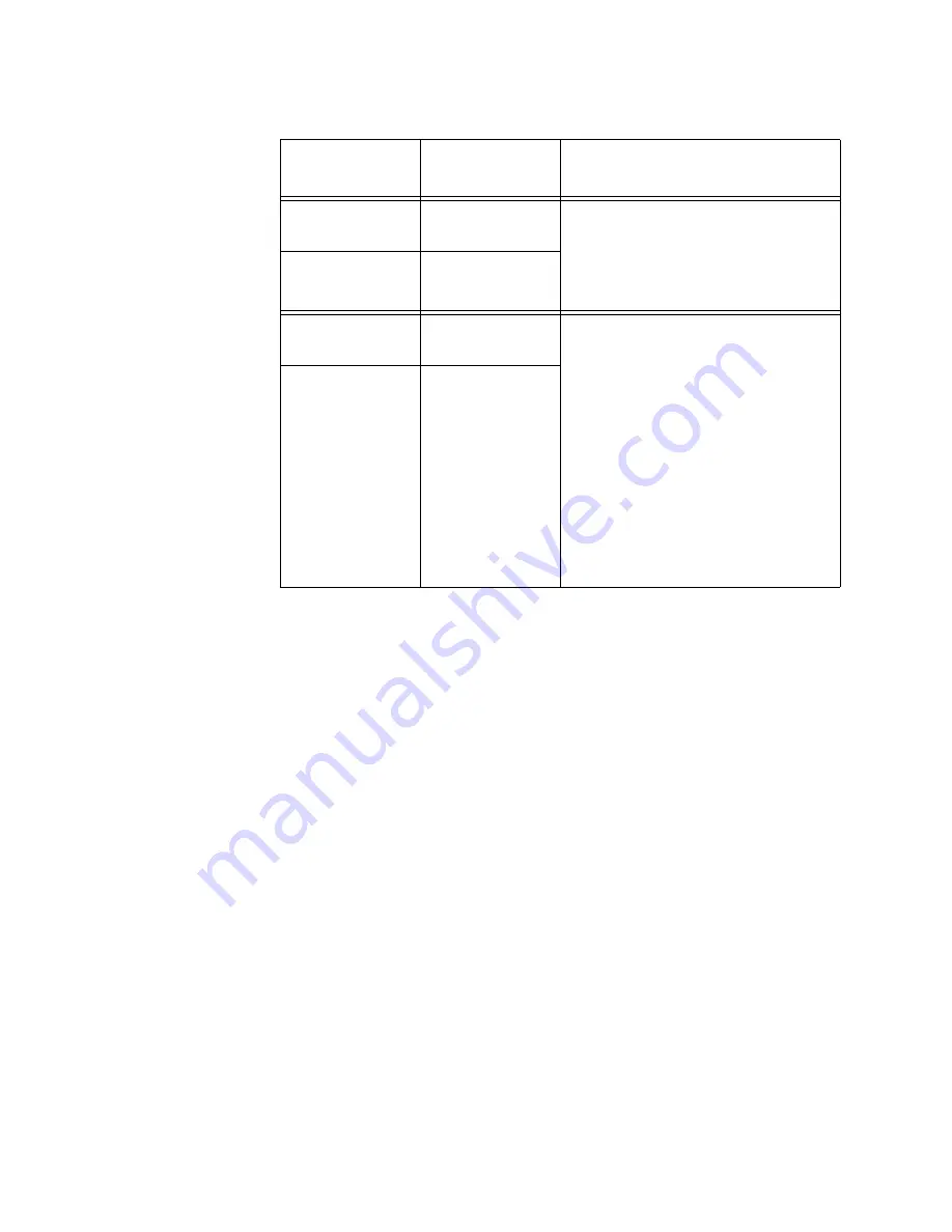
Twisted Pair
Port
Off
The fiber optic port in the channel
can establish a link with its network
device, but the twisted pair port is
unable to establish a link with its
local device.
Fiber Optic Port
Flashing Green
Twisted Pair
Port
Flashing Green
or Amber
Both ports in the channel can
establish links to their network
devices, but one of the ports is
connected to another media
converter that also supports the
Smart MissingLink feature, forming
a chain of converters. A link has
been lost on one of the ports in the
chain, causing a ripple affect
through the chain of converters.
Alternatively, one of the ports is
only able to form an intermittent
link with its network device.
Fiber Optic Port
Flashing Green
Table 10. “L” Link LEDs in the Smart MissingLink Mode (Continued)
Channel Ports
Link LED
States
Description
Summary of Contents for AT-MCF2000
Page 8: ...Contents 8...
Page 12: ...Tables 12...
Page 18: ...Preface 18...
Page 20: ...20 Section I Features...
Page 26: ...Chapter 1 AT MCF2000 Multi channel Media Converter Series 26 Section I Features...
Page 54: ...Chapter 3 AT MCF2012LC AT MCF2012LC 1 and AT MCF2032SP Modules 54 Section I Features...
Page 72: ...Chapter 4 AT MCF2000M Management Module 72 Section I Features...
Page 84: ...Chapter 5 AT MCF2000S Stacking Module 84 Section I Features...
Page 86: ...86 Section II Installation...
Page 90: ...Chapter 6 Reviewing the Safety Precautions 90 Section II Installation...
Page 92: ...Chapter 7 Selecting a Location 92 Section II Installation...
Page 96: ...Chapter 8 Unpacking the AT MCF2000 or AT MCF2300 Chassis 96 Section II Installation...
Page 98: ...Chapter 9 Removing the Rubber Feet 98 Section II Installation...
Page 106: ...Chapter 11 Installing the AT MCF2KFAN Module 106 Section II Installation...
Page 110: ...Chapter 12 Installing a Media Converter Module 110 Section II Installation...
Page 122: ...Chapter 15 Installing the Chassis in an Equipment Rack 122 Section II Installation...
Page 128: ...Chapter 17 Installing the SFP Modules in the AT MCF2032SP Module 128 Section II Installation...
Page 130: ...Chapter 18 Cabling the Ports on the Media Converter Module 130 Section II Installation...
Page 134: ...Chapter 19 Cabling the AT MCF2000M and AT MCF2000S Modules 134 Section II Installation...
Page 138: ...Chapter 20 Powering on the Chassis 138 Section II Installation...
Page 156: ...Chapter 23 Troubleshooting the Modules 156 Section II Installation...
Page 186: ...Appendix C Cleaning Fiber Optic Connectors 186...
Page 190: ...Index 190...


