


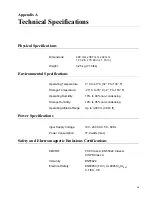


Appendix A: Technical Specifications
50
Connectors and Port Pinouts
This section lists the connectors and connector pinouts for the
AT-9000/24 Gigabit Ethernet Switch and their components.
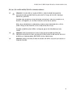
Figure 18 illustrates the pin layout for an RJ-45 connector and port.
Figure 18. RJ-45 Connector and Port Pin Layout
Table 6 lists the RJ-45 pin signals when a twisted pair port is operating in
the MDI configuration.
Table 7 lists the RJ-45 port pin signals when a twisted pair port is
operating in the MDI-X configuration.
Table 8 lists the RJ-45 connector pins and their signals when a
Table 6. MDI Pin Signals (10Base-T or 100Base-TX)
Pin
Signal
1
TX+
2
TX-
3
RX+
6
RX-
Table 7. MDI-X Pin Signals (10Base-T or 100Base-TX)
Pin
Signal
1
RX+
2
RX-
3
TX+
6
TX-
8
8
1
1
Summary of Contents for AT-9000/24
Page 1: ...613 000239 Rev A Layer 2 Gigabit Ethernet Switch AT 9000 24 Installation Guide...
Page 6: ...Contents 6 Appendix B Translated Safety Statements 53...
Page 8: ...Figures 8...
Page 10: ...Tables 10...
Page 28: ...Chapter 1 Overview 28...
Page 46: ...Chapter 2 Installation 46...
Page 48: ...Chapter 3 Troubleshooting 48...
Page 52: ...Appendix A Technical Specifications 52...
Page 74: ...Appendix B Translated Safety Statements 74 1 1 2 3 LAN 4 5 6 I 7 8 9 40 C 10 11 15 LAN OFF 12...