background image

Chapter 2: Installation

44

Starting a Local Management Session

Starting a Local

Management

Session

To start a local management session on an AT-9000/24 Gigabit Ethernet 
Switch, perform the following procedure:

1. Connect one end of the management cable to the console port on the 

switch, as shown in Figure 15.

Figure 15.  Connecting the Console Cable

2. Connect the other end of the cable to the RS-232 port on a terminal or 

PC with a terminal emulator program.

3. Configure the terminal or terminal emulator program as follows:

ˆ

Baud per second: 9600

ˆ

Data bits: 8

ˆ

Stop bits: 1

ˆ

Flow control: None

Note

These default settings are for a DEC VT100 or ANSI terminal, or an 
equivalent terminal emulation program.

801

Summary of Contents for AT-9000/24

Page 1: ...613 000239 Rev A Layer 2 Gigabit Ethernet Switch AT 9000 24 Installation Guide...

Page 2: ...rks or registered trademarks of their respective owners Allied Telesyn Inc reserves the right to make changes in specifications and other information contained in this document without prior written n...

Page 3: ...t installed and used in accordance with this instruction manual may cause harmful interference to radio communications Operation of this equipment in a residential area is likely to cause harmful inte...

Page 4: ...ndice B contiene mensajes de seguridad traducidos para la instalaci n de este equipo Cuando vea el s mbolo vaya al Ap ndice B para ver el mensaje de seguridad traducido a su idioma Important L annexe...

Page 5: ...Workgroup Topology 26 Collapsed Backbone 27 Chapter 2 Installation 29 Reviewing Safety Precautions 30 Selecting a Site for the Switch 32 Cabling 33 Unpacking the Switch 34 Installing the Switch on a...

Page 6: ...Contents 6 Appendix B Translated Safety Statements 53...

Page 7: ...ket 36 Figure 8 Mounting the Switch on the Rack 36 Figure 9 Removing the Dust Plug from the SFP Slot 39 Figure 10 Inserting the SFP 40 Figure 11 Connecting the Twisted Pair Data Cables 41 Figure 12 Re...

Page 8: ...Figures 8...

Page 9: ...10 100 1000Base T Port LEDs 20 Table 4 SFP Port LEDs 21 Table 5 Twisted Pair Cabling and Distances 33 Table 6 MDI Pin Signals 10Base T or 100Base TX 50 Table 7 MDI X Pin Signals 10Base T or 100Base T...

Page 10: ...Tables 10...

Page 11: ...uctions on how to install the AT 9000 24 Gigabit Ethernet Switch This preface contains the following sections Safety Symbols Used in this Document on page 12 Where to Find Web based Guides on page 13...

Page 12: ...uses the safety symbols defined in Table 1 Table 1 Safety Symbols Symbol Meaning Description Caution Performing or omitting a specific action may result in equipment damage or loss of data Warning Pe...

Page 13: ...to Find Web based Guides The installation and user guides for all Allied Telesyn products are available in portable document format PDF on our web site at www alliedtelesyn com You can view the docume...

Page 14: ...Allied Telesyn without an RMA number will be returned to the sender at the sender s expense To obtain an RMA number contact Allied Telesyn Technical Support through our web site www alliedtelesyn com...

Page 15: ...creating or expanding an Ethernet Fast Ethernet or Gigabit Ethernet network This chapter contains the follows sections Features on page 16 Front and Back Panels on page 17 Ports on page 18 LEDs on pa...

Page 16: ...ectors Four combo small form factor pluggable SFP ports Auto MDI MDI X on the twisted pair ports IEEE 802 3 and IEEE 802 3u compliant IEEE 802 3x flow control in full duplex operation back pressure in...

Page 17: ...4 Front Panel Figure 2 illustrates the back panel of the AT 9000 24 Gigabit Ethernet Switch Figure 2 AT 9000 24 Back Panel 10 100 1000Base Twisted Pair Ports Port and System LEDs 793 AT 9000 24 24 Por...

Page 18: ...tting Note In order for the switch to set the duplex mode for each port correctly the end nodes that you connect to the switch ports should also use Auto Negotiation Otherwise a duplex mode mismatch c...

Page 19: ...nstallation Guide 19 RS 232 Console Port The RS 232 console port uses the management cable supplied with the switch Through the console port you can connect to the switch and use the menus based AT S8...

Page 20: ...ceiving power On The switch is receiving power Table 3 10 100 1000Base T Port LEDs LED State Description SPEED On The port is operating at 1000 Mbps Off The port is operating at 10 100 Mbps or no link...

Page 21: ...e 4 describes the LEDs for the SFP ports Table 4 SFP Port LEDs LED State Description LINK ACT Off The port has not established a link with an end node Blinking Green The port is transmitting or receiv...

Page 22: ...ngle AC power supply socket on the back panel which features autoswitch AC inputs To power the switch on or off connect or disconnect the power cord provided with the switch A power cord is supplied w...

Page 23: ...e port number where each address was learned When the switch receives a packet it also examines the destination address and by referring to its MAC address table determines the port on which the desti...

Page 24: ...to half duplex Note Because the ports on the AT 9000 24 Gigabit Ethernet Switch operate in Auto Negotiate mode only the end nodes connected to the switch must also be configured to operate in the Auto...

Page 25: ...on an Ethernet network occurs when two end nodes attempt to transmit data using the same data link at the same time A collision causes end nodes to stop sending data When the switch needs to stop a 10...

Page 26: ...rred to as a power workgroup topology Each workstation or end node is connected directly to a port on the AT 9000 24 Gigabit Ethernet Switch Each end node has a dedicated data link to the switch for b...

Page 27: ...Mbps 1000 Mbps 10 Mbps AT 8000 8POE 8 Port POE Fast Ethernet Switch PoE 9 9R 1 3 5 7 2 4 6 8 TERMINAL PORT 1 3 5 7 2 4 6 8 9 9R POWER 10 100 1000 Base T SFP UPLINK PORT RS 232 DET ON ON 100 LINK ACT 1...

Page 28: ...Chapter 1 Overview 28...

Page 29: ...autions on page 30 Selecting a Site for the Switch on page 32 Cabling on page 33 Unpacking the Switch on page 34 Installing the Switch on a Desktop on page 35 Installing a Switch in a Rack on page 36...

Page 30: ...Do not work on equipment or cables during periods of lightning activity 4 Warning Power cord is used as a disconnection device To de energize equipment disconnect the power cord 5 Warning Class I Equi...

Page 31: ...ing 27 If installed in a closed or multi unit rack assembly the operating ambient temperature of the rack environment may be greater than the room ambient temperature Therefore consideration should be...

Page 32: ...power outlet for the switch should be located near the unit and should be easily accessible The site should provide for easy access to the ports on the front of the switch This will make it easy for y...

Page 33: ...an use either a straight through or crossover twisted pair cable when connecting any network device to a twisted pair port on the switch Table 5 Twisted Pair Cabling and Distances Speed Type of Cable...

Page 34: ...need to return the unit to Allied Telesyn 2 Place the switch on a level secure surface 3 Ensure the following hardware components are included in your switch package If any item is missing or damaged...

Page 35: ...move all equipment from the package and store the packaging material in a safe place 2 Turn the switch over and attach the four rubber feet to the bottom of the switch as shown in Figure 6 Figure 6 At...

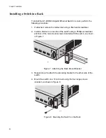
Page 36: ...nstall a bracket on one side of the switch using a Phillips screwdriver and four of the rack mount screws included with the switch as shown in Figure 7 Figure 7 Attaching the Rack Mount Bracket 3 Repe...

Page 37: ...arth ground socket outlet An improperly wired socket outlet could place hazardous voltages on accessible metal parts 6 Pluggable Equipment The socket outlet shall be installed near the equipment and s...

Page 38: ...environment compatible with the manufacturer s maximum rated ambient temperature Tmra 38 Caution Installation of the equipment in a rack should be such that the amount of air flow required for safe o...

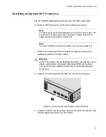
Page 39: ...install the transceiver before you connect cables to it 1 Remove the transceiver from its shipping container and store the packaging material in a safe location Warning An SFP transceiver can be dama...

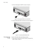
Page 40: ...transceiver Note SFP transceivers are dust sensitive When a fiber optic cable is not installed or when you store the SFP always keep the plug in the optical bores When you do remove the plug keep it...

Page 41: ...h The tab on the connector should lock the connector into place The ports on the switch are auto MDI MDI X You can use either a straight through or crossover twisted pair cable to connect any type of...

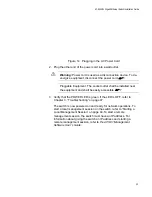
Page 42: ...ver from the SFP 2 Connect the fiber optic cable to the SFP port as shown in Figure 13 Figure 13 Connecting the Fiber Optic Cable Powering On the Switch To power on the switch perform the following pr...

Page 43: ...local management session on the switch refer to Starting a Local Management Session on page 44 To start a remote management session the switch must have an IP address For information about giving the...

Page 44: ...e to the console port on the switch as shown in Figure 15 Figure 15 Connecting the Console Cable 2 Connect the other end of the cable to the RS 232 port on a terminal or PC with a terminal emulator pr...

Page 45: ...password The Main Menu is shown in Figure 17 Figure 17 Main Menu AT 9000 24 Management System Version Local Console Allied Telesyn International Copyright 2005 Login Menu Login AT 9000 24 Local Manag...

Page 46: ...Chapter 2 Installation 46...

Page 47: ...y connecting the unit to another power source Try using a different power cord Verify that the voltage from the power source is within the required levels for your region Verify that the LINK ACT LED...

Page 48: ...Chapter 3 Troubleshooting 48...

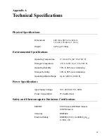
Page 49: ...emperature 20 C to 70 C 4 F to 158 F Operating Humidity 10 to 90 non condensing Storage Humidity 10 to 95 non condensing Operating Altitude Range Up to 3 000 m 9 843 ft Power Specifications Input Supp...

Page 50: ...45 Connector and Port Pin Layout Table 6 lists the RJ 45 pin signals when a twisted pair port is operating in the MDI configuration Table 7 lists the RJ 45 port pin signals when a twisted pair port i...

Page 51: ...Installation Guide 51 1000Base T port is operating at 1000 Mbps Table 8 RJ 45 1000Base T Connector Pinouts Pin Pair Signal 1 1 TX and RX 2 1 TX and RX 3 2 TX and RX 4 3 TX and RX 5 3 TX and RX 6 2 TX...

Page 52: ...Appendix A Technical Specifications 52...

Page 53: ...Handbuch enthaltenen Sicherheitshinweise in mehreren Sprachen Importante Este ap ndice contiene traducciones en m ltiples idiomas de los mensajes de seguridad incluidos en esta gu a Important Cette a...

Page 54: ...et outlet shall be installed near the equipment and shall be easily accessible 8 Caution Air vents must not be blocked and must have free access to the room ambient air for cooling 9 Warning Operating...

Page 55: ...d should be easily accessible 22 Caution To allow proper cooling of the gateway device make sure that the air flow around the unit and through its heatsink cooling fins on the rear is not restricted 2...

Page 56: ...d to install or to replace this equipment 34 Warning The power input must be provided from SELV source only per IEC 60950 Do not connect to a centralized DC battery bank 35 UL recognized wires of 18 A...

Page 57: ...a bathtub washbowl kitchen sink or laundry tub in a wet basement or near a swimming pool Avoid using a telephone other than a cordless type during an electrical storm There may be a remote risk of ele...

Page 58: ...eckdose angeschlossen werden Eine inkorrekt verdrahtete Steckdose kann gef hrliche Spannungen auf zug ngliche Metallteile aufbringen 7 Steckbare Ausr stung Die Steckdose sollte in der N he der Ausr st...

Page 59: ...oder Wasser ausgesetzt werden 20 Vorsicht Bei der Innenraummontage des Gateway Ger ts ist darauf zu achten dass es in einer staubfreien Umgebung installiert wird Es sollte ein Installationsort gew hl...

Page 60: ...Wartungsarbeiten sollten zur Reduzierung des Stromschlagrisikos alle Stromkabel abgetrennt werden 33 Achtung Das Installieren und der Austausch dieser Ausr stung ist nur ausgebildetem und qualifizier...

Page 61: ...ens eines Waschbottichs in einem nassen Kellerraum oder in der N he eines Schwimmbads Vermeiden Sie die Verwendung eines Telefons mit Ausnahme eines schnurlosen Typs w hrend eines Gewitters Es k nnte...

Page 62: ...ligrosas en las piezas met licas accesibles para el usuario 7 El equipo requiere conexi n La toma el ctrica debe estar situada cerca del equipo y ser de f cil acceso 8 Precauci n Las rejillas de venti...

Page 63: ...vo de puerta de enlace De esta forma resultar f cil conectar y desconectar los cables y ver los indicadores LED 21 Atenci n La toma el ctrica de la unidad de puerta de enlace debe estar situada cerca...

Page 64: ...venientemente formado y cualificado 34 Atenci n La alimentaci n s lo debe proceder de una toma SELV conforme a la norma UEC 60950 No conecte la unidad a un banco centralizado de bater as CC 35 El inst...

Page 65: ...ro en un s tano h medo o cerca de una piscina Evite el uso de tel fonos no inal mbricos durante una tormenta el ctrica a fin de evitar el riesgo de electrocuci n como consecuencia de un rayo No utilic...

Page 66: ...re branch e sur une sortie d alimentation correctement mise la terre Dans le cas contraire les pi ces m talliques accessibles risquent d tre soumises des tensions dangereuses 7 quipement connecter La...

Page 67: ...Attention Si le p riph rique servant de passerelle est install l int rieur s assurer qu il se trouve dans en endroit non poussi reux Le site doit offrir un acc s ais au port du p riph rique servant de...

Page 68: ...rocution d brancher tous les cordons d alimentation avant de proc der la maintenance de l unit 33 Avertissement Seul le personnel qualifi et comp tent est autoris installer ou remplacer cet quipement...

Page 69: ...avabo un vier ou un baquet dans un sous sol humide ou pr s d une piscine viter d utiliser le t l phone autre que sans fil en pr sence de foudre pendant un orage La foudre peut entra ner un l ger risqu...

Page 70: ...correttamente cablato e messo a terra Un socket non correttamente cablato potrebbe trasferire voltaggi pericolosi su componenti di metallo accessibili 7 Apparecchiatura cablata Il socket deve essere i...

Page 71: ...i cavi e visualizzare i LED in modo semplice 21 Avvertenza La fonte di alimentazione dell unit gateway deve essere posizionata vicino all unit in un luogo facilmente accessibile 22 Attenzione Per con...

Page 72: ...a 34 Avvertenza L alimentazione deve essere fornita da una fonte SELV come specificato nello standard IEC 60950 Non collegare il dispositivo a una batteria CC centralizzata 35 I cavi riconosciuti UL d...

Page 73: ...simit di acqua ad esempio vicino a vasche da bagno lavabi lavandini piscine oppure in ambienti umidi Non utilizzare un telefono di tipo non cordless durante un temporale esiste il rischio remoto che i...

Page 74: ...Appendix B Translated Safety Statements 74 1 1 2 3 LAN 4 5 6 I 7 8 9 40 C 10 11 15 LAN OFF 12...

Page 75: ...AT GA950 16 and AT GA950 24 Gigabit Ethernet Smart Switches Installation Guide 75 13 14 15 16 17 18 19 20 21 22 23 24 25...

Page 76: ...Appendix B Translated Safety Statements 76 26 UL 600 90 C 14 AWG 27 28 29 30 Allied Telesyn 31 32 33 34 SELV IEC 60950 35 UL 18 AWG 36 UL 22 AWG 37 38 Tmra 39 40...

Page 77: ...AT GA950 16 and AT GA950 24 Gigabit Ethernet Smart Switches Installation Guide 77 41 42 TEL PSTN 43 26 AWG...

Page 78: ...Appendix B Translated Safety Statements 78...

Reviews: