Step 3:
Slide the backcanes up or down to the desired height
As the backcanes are shifted, the back upholstery will move
accordingly. There are a number of holes running vertically through
the lower portion of the backcane. These determine how much the
back height can be raised or lowered.
CAUTION:
For safety reasons, in the highest position the top two bolts must still
pass through the square tubing of the frame and the holes running
through the round tubing of the backcane.
Step 4:
Replace the top two bolts on both backcanes.
Replace all washers. Tighten each bolt and nut to a point where firm
but not crushing the frame.
Step 5:
Replace the third lower bolt on both backcanes if they have been
removed.
3.6
REMOVING THE SEAT OR BACK UPHOLSTERY
3.6.1
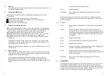
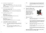
To remove the back upholstery
Step 1:
Remove the rubber grip handles. By
slightly heating them with a hairdryer and
twisting them whilst pulling them off, will
make removing of these easier.
Step 2:
Undo the two screws that are located
underneath the rubber grip handles at the
rear of each back cane (see fig. 3.6.1).
Step 3:
Slightly fold the wheelchair by putting fingers under the middle of the
seat at both front and rear, grasp and give a sharp pull upwards until
the wheelchair is nearly closed.
Step 4:
Slide the back upholstery off the backcanes.
Step 5:
A tension adjustable or custom back can now be fitted.
Step 6:
Once the new back has been fitted slide rubber grip handles back
onto back canes with a twist and push movement, ensuring they're
placed back in their original position.
Figure 3.6.1
3.
MINOR WHEELCHAIR ADJUSTMENTS
3.1
ADJUSTING ARMREST HEIGHT
Standard flip-back armrest:
The armrest flips back by pressing the release lever located at the front base of the
armrest. After you press the release lever (fig 3.1.1), you can you lift the armrest
backwards.
To adjust the height of the armrest, simply pull out the silver bolt located underneath
the armrest pad (see fig 3.1.3) and hold onto it whilst adjusting the height of the
armrest. Release sliver bolt once desired height is achieved to securely lock armrest
back in place (see fig 3.1.4).
3.2
QUICK RELEASE REAL WHEELS
3.2.1
To remove rear wheel ensure the brake is off.
Step 1:
Support the weight of the
wheelchair with one hand by
holding the push handle.
Step 2:
Push the hub cover and hold
Figure 3.1.1
Figure 3.1.2
Figure 3.1.3
Figure 3.1.4
Figure 3.2
Page 6
Page 9
4.
MAINTENANCE
4.1
CLEANING AND TYRE CARE
4.1.1
Cleaning
Clean the upholstery with a biological cleaning agent such as is recommended for
cleaning kitchen work surfaces. Do not use any propriety cleaning fluids as these may
damage the upholstery. Clean chrome and painted surfaces with a wax polish spray
or simply wipe over with a clean soft duster.
4.1.2
Tyres
The KM8000 manual wheelchair is fitted with a maintenance free castor and 12 ½” x
2 ¼” pneumatic rear tyre (transit wheelchair) or a 24” x 2 ¼” pneumatic rear tyre
(self-propelling wheelchair). It is advisable to check the air pressure of these
components every two weeks. This can be done either at a service station or with a
standard bicycle pump.
4.2
MAINTENANCE CHECKS
Every week check the following items for damage or excessive wear:
Upholstery and occupant restraints where fitted.
Every month examine the following items for effective operation e.g. damage and
general wear and tear:
Seat and backrest cushions
Armrest latch lever and clamp handle
Armrest pads
Brakes
Antitippers
Castors for free rotation of castor wheel and castor unit
Tyre tread depth
For repairs, please contact your service contractor.
2.1.3
Footrest Adjustments
Footrest Removal and Refitting
To remove the footrest push/pull the release lever and rotate the footrest until it faces
outwards. To lift off, pull upwards.
To refit, locate the footrest unit onto the frame lugs (at about 90 degrees to the side of
the frame) and rotate it inwards until the unit locks into place (you will hear a click).
CAUTION:
The occupant's leg must be supported or resting safely, while
executing the above adjustments.
To adjust footplate height
Step 1:
To adjust footplate height, use tool
provided to loosen the bolt at the
bottom of the footrest stem.
Step 2:
Adjust to the required height and
retighten.
2.1.4
Antitip bars for wheelchair
NOTE: For the users safety, these must be fitted.
To fit: Depress rear location button on the antitip bar
and slide into rear of frame tube. The front button
MUST engage through the hole in the frame. Check
antitip is secure by attempting to push backward and
forward. Follow these instructions to fit the atnitip bar
on the other side of the wheelchair.
2.2
GETTING IN AND OUT
2.2.1
Getting in
Step 1:
Engage both brakes.
Step 2:
Lift up the footplates and swing footrest to the side.
Step 3:
The user should now lower themselves into the seat using the
armrests as supports (if possible).
Step 4:
Push the footplates back down and re-locate the footrests so that
Page 3
Page 12
6
7


