background image

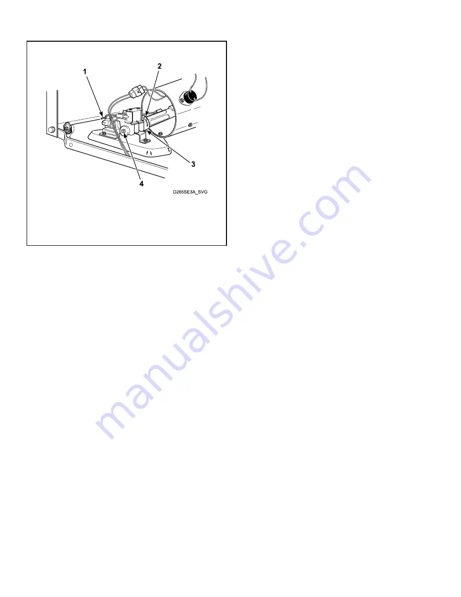
Gas Shut-Off Valve Only Applicable on Certain Mod-
els

1.  

Shut-off Valve Handle

2.  

Air Shutter Lockscrew

3.  

Air Shutter

4.  

1/8" Pipe Plug (For checking manifold pressure)

Figure 4

Adjustments

©

 Copyright, Alliance Laundry Systems LLC -

 DO NOT COPY or TRANSMIT

  40

  Part No. D515517ENR3

Summary of Contents for ZDE3SRGS173CW01

Page 1: ...rs DRY726C_SVG Original Instructions Keep These Instructions for Future Reference CAUTION Read the instructions before using the machine If this machine changes ownership this manual must accompany ma...

Page 2: ......

Page 3: ...edly Gas Dryer Models 23 Igniter Glows but Burner Does Not Ignite Gas Dryer Models 24 Dryer Heater Assembly or Burner Shuts Off Prematurely 25 Dryer Heater Assembly or Burner Repeatedly Cycles Off On...

Page 4: ...ls 47 Electrical Circuit Ignition System Gas Models 48 Gas Valve Coils Check Gas Models 48 Sensor Check Gas Models 49 Igniter Check Gas Models 49 Thermal Fuse Electric Models 49 Heater Assembly Electr...

Page 5: ...according to the manufacturer s instruc tions may result in conditions which can produce serious injury death and or property damage Do not repair or replace any part of the product or attempt any se...

Page 6: ...and Locating an Authorized Service Person Alliance Laundry Systems is not responsible for personal injury or property damage resulting from improper service Review all service information before begin...

Page 7: ...01 ADLE9RGS303XW34 ADE3SRGS173TW01 ADEE9BSS543FN01 ADGE9BGS115CW14 ADLE9RGS305XW34 ADE3SRGS175CW01 ADEE9RGS173CW01 ADGE9BGS115TW01 ASEE8AGW173TW01 ADE3SRGS175CW14 ADEE9RGS173TW01 ADGE9BGS123DW01 ASGE8...

Page 8: ...RGS113CW01 ADEE9BGS453NW36 ADG3SRGS115CW01 ADGE9RGS115CW14 ZDGE8RGS113FW01 ADEE9BGS455NW36 ADG3SRGS115CW14 ADGE9RGS115FW01 ZDGE8RGS115FW01 ADEE9BGS543DW01 ADG3SRGS115TW01 ADGE9RGS115TW01 ZDGE9BGS113CW...

Page 9: ...At cycle start when fabric is wet and the temperature inside dryer is cool the heat source burner on gas models and heating element on electric models is energized and heats the cylinder until operati...

Page 10: ...even with an empty load When the heating element shuts off meter should read 120 Volts and the timer motor should advance the cycle 7 If meter does not read 120 Volts after the unit has reached proper...

Page 11: ...UG dryer Remove Red Black striped wire from terminal T on timer and perform an ohms check between the timer wire and the cycling thermostat ter minal where the Red Black stripe wire attaches on the cy...

Page 12: ...to check voltage using a multimeter Refer to the washer s serial plate to determine proper voltage it is designed to operate on Refer to Figure 1 for serial plate location Troubleshooting Flowcharts C...

Page 13: ...ycle Yes Are motor starting functions inoperative does not start or motor just hum No Test timer electronic control and replace if inoperative Yes Is motor dead won t run No Refer to Adjustments secti...

Page 14: ...ll spin Replace motor if shaft is locked up Yes Is wiring broken loose or incorrect No Firmly press connection block onto motor switch Yes Is power cord miswired No Refer to wiring diagram Yes Refer t...

Page 15: ...n loose or incorrect wiring No Check cylinder for binding and out of round condition front and rear bulkheads for warping support rollers for binding cylinder seals and glides for wear or damage and c...

Page 16: ...nding Check cylinder seals and glides for wear or damage Yes Is belt routed on wrong side of idler lever No Replace or reconnect spring Yes Is there oil on cylinder No Reroute belt Yes Is belt inside...

Page 17: ...arts manual for correct motor part number Yes Is idler arm bent No Check belt part number against correct part number in parts manual and replace belt if needed Yes Replace idler arm Yes Troubleshooti...

Page 18: ...door switch inoperative No Remove dust or lint and spray with a cleaner and lubricant Yes Is timer electronic control inoperative No Test switch and replace if inoperative Yes Test timer electronic c...

Page 19: ...Door is Open Is door switch miswired Replace door switch No Rewire door switch Refer to wiring diagram Yes Troubleshooting Flowcharts Copyright Alliance Laundry Systems LLC DO NOT COPY or TRANSMIT 19...

Page 20: ...noperative Yes Is limit thermostat inoperative No Reset timer electronic control Try another cycle Yes Is drive motor switch inoperative No Test thermostat and replace if inoperative Yes Electric Mode...

Page 21: ...o Dryer Test Procedures section Yes Gas Models Is gas flow in gas orifice restricted Yes Check harness connections to gas valve coils sensor and main harness Reconnect as required No Is cycling thermo...

Page 22: ...lve pink and blue wires Has flame sensor failed with contacts open Yes Check thermostats motor switch and wiring No Is igniter broken or open No Replace sensor Yes Replace igniter Yes Troubleshooting...

Page 23: ...plied with unit for exhaust requirements Yes Is gas supply insufficient Yes Replace sensor or correct gas supply problem No Is igniter cracked No Check gas supply and pressure Make sure gas shut off v...

Page 24: ...section Yes Are igniter and bracket improperly installed on burner tube assembly No Check gas supply and pressure Make sure gas shutoff valve is turned on Yes Is sensor improperly installed on burner...

Page 25: ...ersion Procedures supplied in gas burner conversion kit No Cycling off on limit thermostat No Adjust flame Refer to Adjustments section Yes Gas Models Is sensor contact closing No Momentarily connect...

Page 26: ...Troubleshooting Flowcharts Copyright Alliance Laundry Systems LLC DO NOT COPY or TRANSMIT 26 Part No D515517ENR3...

Page 27: ...dryer ductwork and clean Yes Is hinged damper on exhaust system weather hood not free to open No Disassemble and clean exhaust system Yes Is limit thermostat cycling at too low a temperature No Free h...

Page 28: ...ylinder seal s Is there an air leak at front panel seal No Check and replace seal s if necessary Yes Check and replace seal if necessary Yes Troubleshooting Flowcharts Copyright Alliance Laundry Syste...

Page 29: ...t switch and replace if inoperative Yes Is wiring incorrect No Refer to Dryer Motor Does Not Stop paragraph Yes Has heater assembly shorted No Refer to wiring diagram Yes Remove heater assembly and ch...

Page 30: ...Yes Electronic control models Is cycle selector or control inoperative No Test and replace switch or timer if inoperative Yes Is exhaust system improper or inadequate No Test and replace cycle select...

Page 31: ...ued from previous page Is belt installed improperly low RPM Check for proper installation Yes Troubleshooting Flowcharts Copyright Alliance Laundry Systems LLC DO NOT COPY or TRANSMIT 31 Part No D5155...

Page 32: ...iring broken loose or incorrect No Timer will not advance until the load is almost dry Yes Timer models Is timer motor inoperative No Refer to wiring diagram Yes Electronic control Is control inoperat...

Page 33: ...om previous page Are there air leaks Check and fix any gap between air duct and filter mounting Yes Troubleshooting Flowcharts Copyright Alliance Laundry Systems LLC DO NOT COPY or TRANSMIT 33 Part No...

Page 34: ...trol inoperative not allowing cooldown No Test cycling thermostat and replace if inoperative Yes Are seals inoperative No Test timer electronic control and replace if inoperative Yes Are there air lea...

Page 35: ...to normal cycle and allow it to heat to operating temperature If the belt vibrates as it rotates around the cylinder replace the idler spring Yes Are rollers worn No Replace idler pulley and shaft Yes...

Page 36: ...issing or cracked fan blades No If the abnormal operating noise is loudest at the vent exit the problem is originating from the blower housing Replace the current housing and cover Yes Troubleshooting...

Page 37: ...ermis tor circuit is sensed as being shorted Remove any lint build up around thermistor Check wire harness con nection between thermistor and har ness Unplug dryer or turn circuit breaker off on to cl...

Page 38: ...e the dip switch 1 setting may need to be changed If the dip switch 1 setting is changed power down ma chine power up and try again Er id Board ID error In correct replacement control Terminate cycle...

Page 39: ...he dryer MUST NOT rock IMPORTANT DO NOT move the dryer at any time unless the dryer is completely assembled DO NOT slide the dryer across the floor once the leveling legs have been extended as the leg...

Page 40: ...on Certain Mod els 1 Shut off Valve Handle 2 Air Shutter Lockscrew 3 Air Shutter 4 1 8 Pipe Plug For checking manifold pressure Figure 4 Adjustments Copyright Alliance Laundry Systems LLC DO NOT COPY...

Page 41: ...f OFF position and into cycle 3 Set test meter to read Ohms The following readings should be found a Motor circuit test L1 and M zero Ohms closed b Heat circuit test L2 and H zero Ohms closed c Timer...

Page 42: ...FABRIC SELECTOR SWITCH 3 Position L1 2 L1 3 L1 1 No Heat X Delicate X X Perm Press Regular X X indicates closed Drive Motor Refer to Figure 7 1 Remove motor and exhaust assembly 2 Disconnect motor wir...

Page 43: ...ing inoperative motor switch W290 NOTE Disconnect terminal 5 wire yellow or copper from motor switch before testing start terminals NOTE Reconnect terminal 5 wire yellow or copper to motor switch befo...

Page 44: ...copper wire Yes Inoperative start switch Replace switch No Run Terminals Manually depress actuator Continuity exists between switch terminal 6 and terminal 5 yellow or copper wire Yes Inoperative sta...

Page 45: ...e motor No All motor windings check O K Yes Inoperative protector Replace motor No Motor Switch 1 Remove motor and exhaust fan assembly 2 Remove the two motor switch attaching screws Refer to Fig ure...

Page 46: ...itch onto motor and reconnect motor switch leads removed in Step 2 Refer to Figure 8 6 Test motor switch by following the step by step procedures Refer to Drive Motor 7 Before reinstalling the motor a...

Page 47: ...valve and a secon dary coil valve The split coil valve is opened when the dryer thermostat calls for heat while the secondary valve does not open until the igniter has attained ignition temperature 2...

Page 48: ...e valve wire harness disconnect block from the hold ing and booster coil Refer to Figure 12 5 Plug dryer power cord into wall receptacle and start the dryer in a heat setting refer to the Operating In...

Page 49: ...xamine all wires terminals and connectors to be sure wiring is correct before replac ing any components 1 Igniter and Bracket 2 Attaching Screw 3 White Ceramic Portion Figure 13 Thermal Fuse Electric...

Page 50: ...supporting the access panel remove two screws from bottom edge of access panel 2 Gently lower the access panel to disengage locators from bot tom edge of front panel 3 Remove two screws holding botto...

Page 51: ...lve to gas dryer before serv icing Never start the Dryer with any guards panels re moved Whenever ground wires are removed during serv icing these ground wires must be reconnected to ensure that the d...

Reviews: