Rockwell Automation Publication 750-IN020D-EN-P - May 2017
45
PowerFlex 755 IP00, NEMA/UL Open Type Drive
External Power Supply Connections
Power Wiring
Grounding Requirements
The drive Safety Ground-PE must be connected to system ground.
Ground
impedance must conform to the requirements of national and local industrial
safety regulations and/or electrical codes. The integrity of all ground connections
should be periodically checked.
Recommended Grounding Scheme
A single point (PE only) grounding scheme should be used. Some applications
may require alternate grounding schemes, see Wiring and Grounding Guidelines
for Pulse-width Modulated (PWM) AC Drives, publication
for more information. These applications include installations with long
distances between drives or drive line-ups, which could cause large potential
differences between the drive or line-up grounds.
For installations within an enclosure, a single safety ground point or ground bus
bar connected directly to building steel should be used. All circuits including the
AC input ground conductor should be grounded independently and directly to
this point/bar.
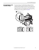
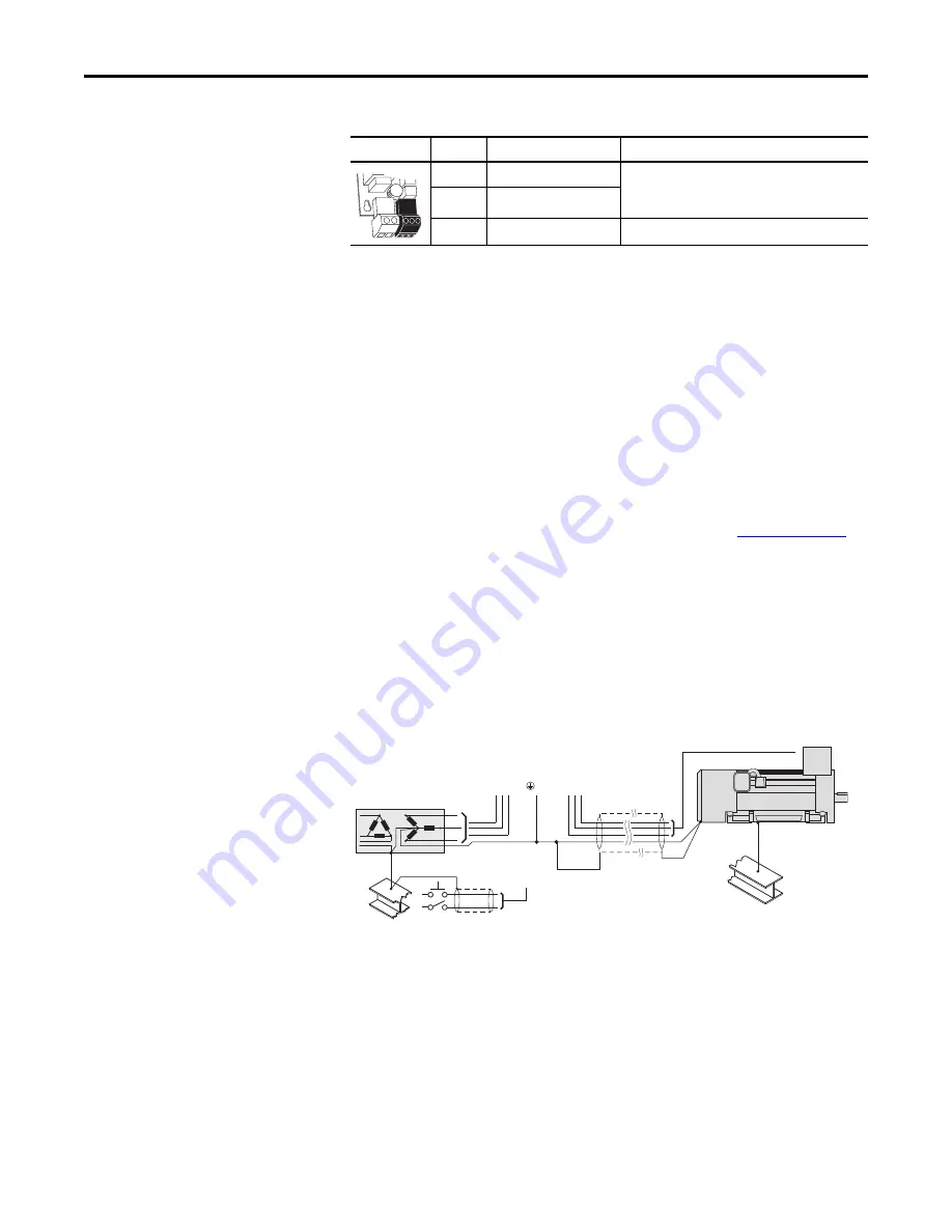
Typical Grounding
Shield Termination - SHLD
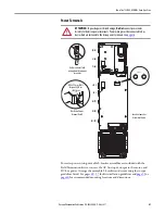
The Shield terminal provides a grounding point for the motor cable shield. It
must be connected to an earth ground by a separate continuous lead. The
motor
cable
shield should be connected to this terminal on the drive (drive end) and the
motor frame (motor end). Use a shield terminating or EMI clamp to connect
shield to this terminal.
Power Block
Terminal
Name
Description
AP+
+24 Volt Auxiliary Power
Connections for user supplied power supply: 24V DC
±10%, 5 A, PELV (Protective Extra Low Voltage) or SELV
(Safety Extra Low Voltage)
AP–
Auxiliary Power Common
Sh
Shield
Terminating point for wire shields.
AP+
AP–
Sh
U (T1)
V (T2)
W (T3)
R (L1)
S (L2)
T (L3)
PE
SHLD


