


2
Rockwell Automation Publication 440R-IN079C-EN-P - May 2020
MSR127 Minotaur Monitoring Safety Relays Installation Instructions
Safety Input
The safety input can be single channel or dual channel. According to the wiring
inputs, cross-loop monitoring of the inputs is enabled or disabled. Crossloop
monitoring can be enabled for 2-channel safety inputs in 4wire connection
S11-S12, S21-S22. Cross-loop monitoring is disabled for single-channel inputs,
dual-channel inputs in 3-wire connection and 24V DC signals. With external 24V DC
signals, the negative pole must be connected to S21.
Reset
Reset modes — Unit is available with automatic/manual start (MSR127T/TP) and
manual monitored reset (MSR127R/RP).
A valid start/reset can only be operated if the feedback circuit is closed. Feedback
contacts of controlled actuators are connected in series with start/reset circuit
(S12-S34).
T - Automatic/manual Start
In automatic/manual start mode, the reset circuit S12-S34 is not monitored against
signal changes (no edge detection). The reset circuit can be closed before or after
the safety inputs are closed. Unit is active once the safety inputs are closed and
the reset circuit has been closed. If the safety inputs and reset circuit are
concurrently closed during powerup, unit is activated immediately.
R - Manual Monitored Reset
In manual monitored reset mode, a signal change of the reset circuit (S12-S34) is
required and monitored. The reset circuit must be closed after the safety inputs
are closed.
Positive Edge
Unit is active once the safety inputs are closed and then the reset circuit is closed.
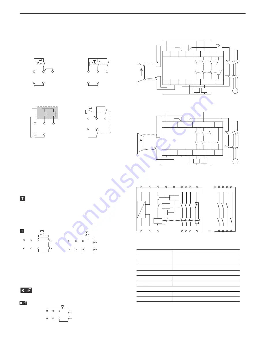
Wiring Examples
Figure 1 - Dual-channel Safety Gates, Monitored Manual Reset,
Monitored Output
Figure 2 - Dual-channel Safety Gates, Auto Reset, Monitored Output
Circuit Diagram
S11 S52 S12
S21 S22
A1
A2
24V
DC
S11 S52 S12
S21 S22
S11 S52 S12
S21 S22
Max PLc: single-channel; N.C.
Max PLd: dual-channel; 3-wire connection
Max PLe: dual-channel; 24V DC
signal
Max PLe: dual-channel; 4-wire connection,
cross faults require fault reset
S11 S52 S12
S21 S22
S11 S52 S12
S21 S22 S34
K1
K2
MSR127
MSR127.1
S11 S52 S10
S21 S22 S33
K1
K2
S11 S52 S12
S21 S22 S34
MSRxxxR
K1
K2
440R-xxxxM
Table 1 - Connections
Terminal
Description
A1, A2
Power
S11, S12 (S10), S52, S21, S22
Safety input (N.C.)
S34 (S33)
Monitoring feedback loop with Reset button
MSR127R, MSR127T, MSR127RP, MSR127TP
13, 14, 23, 24, 33, 34
Safety output (N.O.)
41, 42
Auxiliary output (N.C.)
MSR127.1T
13, 14, 23, 24
Safety output (N.O.)
33, 34, 43, 44
Auxiliary output (N.O.)
L1L2L3
S21 S22 S34 A2 14 24 34 42
A1 S11 S52 S12 13 23 33 41
K1
K2
K1
K2
Open
Closed
N
Reset
L1
M
max PLe, SIL3
MSR 127RP
A1 S11 S52 S10 13 23 33 43
S21 S22 S33 A2 14 24 34 44
Open
Closed
+24V
K1
K1
K2
K2
L1L2L3
M
MSR127.1T
max PLe, SIL3
Reset
A1
S11 S52 S12
(S10)
S34
(S33)
13 23 33 41
K2
K1
A2
S21 S22
14 24 34 42
…S34
13 23 33 43
14 24 34 44
MSR127/(MSR127.1)
MSR127.1