


122
Rockwell Automation Publication 2198-UM002E-EN-P - February 2018
Chapter 5
Connect the Kinetix 5700 Drive System
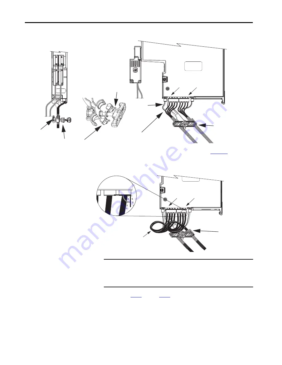
Figure 78 - Dual-axis Inverter Cable Installation (16 and 14 AWG cable)
12 and 10 AWG (series A) cables, prepared as shown on
, and series B
cables have longer conductors that support service loops.
Figure 79 - Dual-axis Inverter Cable Installation (series A and B, 12 and 10 AWG cable)
4.
Repeat
through
for each dual-axis inverter.
UFB-A
UFB-B
D+
D-
D+
D-
MF-A
MF-B
Clamps Compressed
Around Shields Close
to the Heat Shrink
Nylon Rivet
Dual-axis Inverter
(side view)
Clamp Spacer
2198-K57CK-D15M
Connector Kit
Dual-axis Inverter
(front view)
Universal Feedback
(UFB) Connectors
Clamp Knob
Motor Power (MP) and
Motor Brake (BC) Connectors
Bulletin 2090-CPBM7DF
Power/Brake Cables
Conductors enter into the motor and brake connectors at
approximately 90° (between 75° and 105° is acceptable).
Stress Relief
Bends
Clamps Compressed
Around Shields Close
to the Heat Shrink
Dual-axis Inverter
(side view)
Motor Power (MP) and
Motor Brake (BC) Connectors
Bulletin 2090-CPBM7DF
Power/Brake Cables
Service loops provide stress relief and the
conductors enter into the motor and
brake connectors at approximately 90°
(between 75 and 105° is acceptable).
75°…105°
Entry Into
Connectors
IMPORTANT
Avoid sharp bends in the power and brake conductors. You must route
the power and brake conductors from where they exit the clamp and
enter the motor and brake connectors so that stress-relief bends or
service loops are formed.