


Chapter 2
Behavior models used in CIP Motion
56
Rockwell Automation Publication MOTION-RM003I-EN-P - February 2018
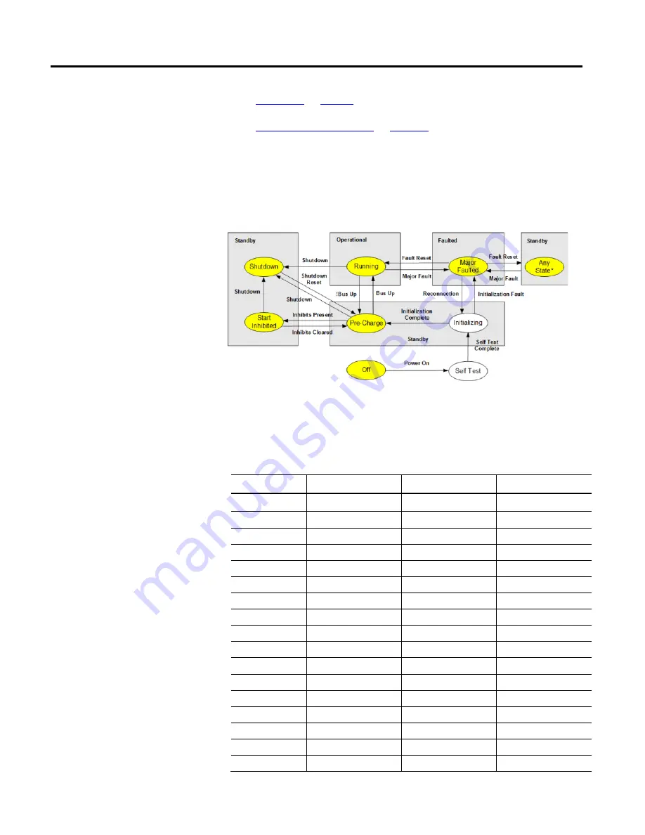
When the Motion Device Axis Object is associated with a CIP Motion
Converter, the Active Control state diagram reduces to the following diagram.
Shaded regions show mapping of Axis States to corresponding Identity Object
states. State transitions terminating on shaded boxes can transition to any axis
state within the box.
Tip:
*Specific Standby state after a fault reset is determined by applying Fault Reset State
Transition Precedence rules.
Valid transitions for the Axis State Model of a CIP Motion Converter axis are
explicitly defined in the following table:
Current State
Event
Conditions
Next State
Off
Power Up
Self Test
Self Test
Self Test Complete
Initializing
Initializing
Initialization Fault
Major Faulted
Initializing
Initialization Complete
Pre-Charge
Shutdown
Major Fault
Major Faulted
Shutdown
Shutdown Reset
Pre-Charge
Start Inhibited
Shutdown
Shutdown
Start Inhibited
Major Fault
Major Faulted
Start Inhibited
Inhibits Cleared
Pre-Charge
Pre-Charge
Start Inhibit
Start Inhibited
Pre-Charge
Shutdown
Shutdown
Pre-Charge
Major Fault
Major Faulted
Pre-Charge
Bus Up
Running
Major Faulted
Fault Reset
Shutdown = 1
Shutdown
Major Faulted
Fault Reset
Shutdown = 0
Pre-Charge
Major Faulted
Reconnection
Initializing
Running
Not Bus Up
Pre-Charge
CIP Motion Converter Axis
Behavior Model