142
Rockwell Automation Publication 1756-UM022D-EN-P - May 2017
Chapter 9
Monitor Status and Handle Faults
The Safety Status button itself indicates whether the controller is safety-locked
or -unlocked, or faulted. It also displays an icon that shows the safety status.
Icons are green when the controller is safety-locked, yellow when the controller
is safety-unlocked, and red when the controller has a safety fault. When a safety
task signature exists, the icon includes a small checkmark.
Monitor the Connections
You can monitor the status of standard and safety connections.
All Connections
If communication with a device in the I/O configuration of the controller does
not occur for 100 ms, communication times out and the controller produces
the following warnings:
• The I/O indicator on the front of the controller flashes green.
• An alert symbol
shows over the I/O configuration folder and over
the device that has timed out.
• A device fault is produced that you can access through the Connections
tab of the Module Properties dialog box for the device or via the GSV
instruction.
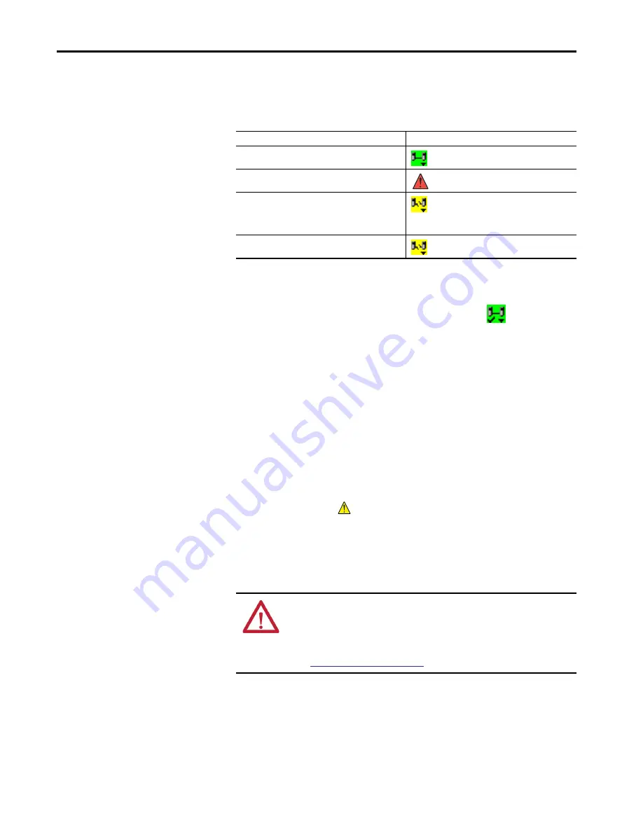
Table 44 - Safety Status Icon
If the safety status is
This icon is displayed
Safety Task OK
Safety Task Inoperable
Partner Missing
Partner Unavailable
Hardware Incompatible
Firmware Incompatible
Offline
ATTENTION:
Safety I/O and produce/consume connections cannot be
configured to automatically fault the controller when a connection is lost.
Therefore, you need to monitor for connection faults to be sure that the
safety system maintains SIL 3/PLe integrity.
See
Summary of Contents for GuardLogix 5570
Page 8: ...8 Rockwell Automation Publication 1756 UM022D EN P May 2017 Table of Contents...
Page 20: ...20 Rockwell Automation Publication 1756 UM022D EN P May 2017 Chapter 1 System Overview Notes...
Page 169: ...Rockwell Automation Publication 1756 UM022D EN P May 2017 169 Index Notes...
Page 170: ...170 Rockwell Automation Publication 1756 UM022D EN P May 2017 Index Notes...
Page 171: ......


