Allen-Bradley FLEX I/O 1794-OB8EP Installation Instructions Manual Download Page 1

  %  &$!$ #

#(   '&#!&#" "

' &#"    ) 


(Cat. No. 1794-OB8EP)


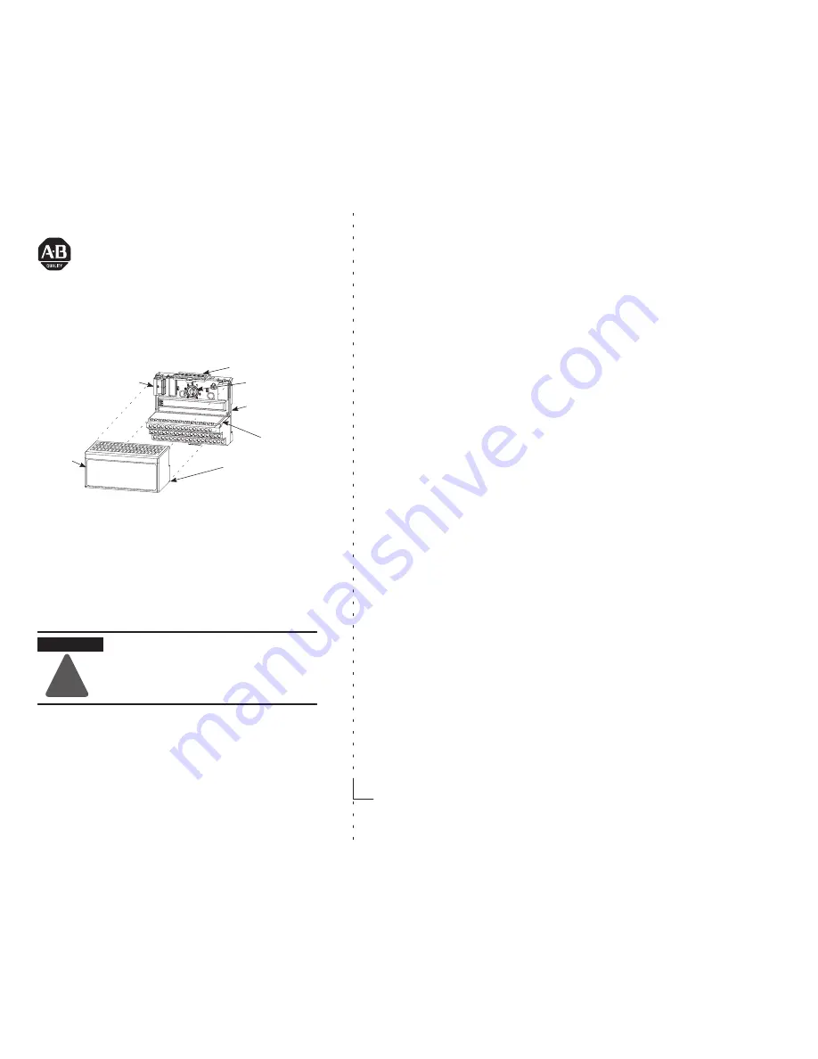
This module mounts on a 1794 terminal base unit.

1. Rotate keyswitch (1) on terminal base unit (2) clockwise to position 2

as required for this type of module.

2. Make certain the flexbus connector (3) is pushed all the way to the left

to connect with the neighboring terminal base/adapter. You cannot
install the module unless the connector is fully extended.

3. Make sure that the pins on the bottom of the module are straight so

they will align properly with the connector in the terminal base unit.

WARNING

!

If you remove or insert the module while the
backplane power is on, an electrical arc can occur.
This could cause an explosion in hazardous location
installations. Be sure that power is removed or the
area is nonhazardous before proceeding.

4. Position the module (4) with its alignment bar (5) aligned with the

groove (6) on the terminal base.

Installation Instructions

Summary of Contents for FLEX I/O 1794-OB8EP

Page 1: ...the connector is fully extended 3 Make sure that the pins on the bottom of the module are straight so they will align properly with the connector in the terminal base unit WARNING If you remove or insert the module while the backplane power is on an electrical arc can occur This could cause an explosion in hazardous location installations Be sure that power is removed or the area is nonhazardous b...

Page 2: ...ectual property liability for actual use based upon the examples shown in this publication Allen Bradley publication SGI 1 1 Safety Guidelines for Application Installation and Maintenance of Solid State Control available from your local Allen Bradley office describes some important differences between solid state equipment and electromechanical devices that should be taken into consideration when ...

Page 3: ...upplied as open type equipment It must be mounted within an enclosure that is suitably designed for those specific environmental conditions that will be present and appropriately designed to prevent personal injury resulting from accessibility to live parts The interior of the enclosure must be accessible only by the use of a tool Subsequent sections of this publication may contain additional info...

Page 4: ...iststrap Do not touch connectors or pins on component boards Do not touch circuit components inside the equipment If available use a static safe workstation When not in use keep modules in appropriate static safe packaging ATTENTION Remove field side power before removing or inserting this module This module is designed so you can remove and insert it under backplane power When you remove or inser...

Page 5: ... A 2 Connect the associated return to the corresponding terminal on the 16 33 row B or to the odd numbered terminals on the 0 15 row A as indicated in the wiring table below Returns are internally connected together 3 Connect 24V dc power to terminal 34 on the 34 51 row C 4 If continuing power to the next terminal base unit connect a jumper from terminal 51 24V dc on this base unit to terminal 34 ...

Page 6: ...B Row C 39 40 41 42 43 44 45 46 0 AĆ0 AĆ11 BĆ17 1 AĆ2 AĆ31 BĆ19 2 AĆ4 AĆ51 BĆ21 3 AĆ6 AĆ71 BĆ23 4 AĆ8 AĆ91 BĆ25 5 AĆ10 AĆ111 BĆ27 6 AĆ12 AĆ131 BĆ29 7 AĆ14 AĆ151 BĆ31 A output terminals B common terminals C Power terminals CĆ34 thru 51 for 1794ĆTB3 1 AĆ1 3 5 7 9 11 13 and 15 are connected together inside the module to 24V dc common ATTENTION Total current draw through the terminal base unit is limi...

Page 7: ...ls 0 thru 14 on row B 2 Connect customer load returns to odd numbered terminals 1 thru 15 on row C as indicated in the table below 3 Connect 24V dc return to terminal 16 on row B 4 If continuing the dc return bus to the next terminal base unit connect a jumper from terminal 33 on this base unit to terminal 16 on the next base unit 5 Connect 24V dc power to terminal 34 on row C 6 If continuing dc p...

Page 8: ...bit 08 cycle backplane power The reset function resets all output fault bits simultaneously Non faulted outputs remain unaffected during the reset Using the Fault Reset Button When you press the manual reset button the fault indicator for the faulted output turns off for about 1 2s the faulted output will not attempt to turn on during this delay after the 1 2s delay the faulted output attempts to ...

Page 9: ...tput 0 O1 corresponds to output 2 etc FR fault reset bit 1 reset output 0 no change Note The unused lower byte in read word 1 floats during operation Do not use this byte for fault status See Programming below Programming If your program automatically checks for fault bits bits 8 through 15 of read word 1 must be masked This is a sample program for a module at rack address 1 group 0 Add similar ru...

Page 10: ...t contains batteries they must only be changed in an area known to be nonhazardous Informations sur l utilisation de cet équipement en environnements dangereux Les produits marqués CL I DIV 2 GP A B C D ne conviennent que une utilisation en environnements de Classe I Division 2 Groupes A B C D dangereux et non dangereux Chaque produit est livré avec des marquages sur sa plaque d identification qui...

Page 11: ...hannel Surge Current 4A for 10ms repeatable every 3 seconds see chart OFFĆstate Leakage 0 5mA maximum ONĆstate Voltage Drop 0 2V dc maximum Isolation Voltage minimum Tested to 850V dc for 1s between user and system No isolation between individual channels Output Signal Delay1 Off to On On to Off 0 1ms maximum 0 1ms maximum Flexbus Current maximum 73mA Power Dissipation 5 5W maximum 31 2V Thermal D...

Page 12: ... 2 14 Test Na Unpackaged Nonoperating Thermal Shock 40 to 185 F 40 to 85 C Relative Humidity IEC 60068 2 30 Test Db Unpackaged Nonoperating Damp Heat 5 to 95 noncondensing Shock Operating Nonoperating IEC 60068 2 27 Test Ea Unpackaged Shock 30g 50g Vibration IEC 60068 2 6 Test Fc Operating 5g 10 500Hz ESD Immunity IEC 61000 4 2 4kV contact discharges 8kV air discharges Radiated RF Immunity IEC 610...

Page 13: ... EMC Directive compliant with EN 61000 6 4 Industrial Emissions EN 50082 2 Industrial Immunity EN 61326 Meas Control Lab Industrial Requirements EN 61000 6 2 Industrial Immunity C Tick3 Australian Radiocommunications Act compliant with AS NZS 2064 Industrial Emissions 1 Off on delay is time from a valid output on signal to output energization On off delay is time from a valid output off signal to ...

Page 14: ...eport No 28 682 010 Compliance with the Essential Health and Safety Requirements has been assured by compliance with EN 50021 1999 IMPORTANT Observe the following additional Zone 2 certification requirements This equipment is not resistant to sunlight or other sources of UV radiation The secondary of a current transformer shall not be open circuited when applied in Class I Zone 2 environments Equi...

Page 15: ...24V dc FLEX I O Electronically Fused 8 Output Module 15 ...

Page 16: ... 2002 With major offices worldwide World Headquarters AllenĆBradley 1201 South Second Street Milwaukee WI 53204 USA Tel 1 414 382Ć2000 Fax 1 414 382Ć4444 1794 IN020B EN P May 2002 Supersedes publication1794Ć5 20 April 1999 PN957678 95 Copyright 2002 AllenĆBradley Company Inc Printed in USA ...

Reviews: