


Rockwell Automation Publication 1756-UM540E-EN-P - December 2017
65
Temperature-sensing Analog Modules
Chapter 4
Underrange/Overrange Detection
This feature detects when a temperature-measuring input module is operating
beyond limits set by the input range. For example, if you are using the module in
the 0…1000
Ω
input range and the module resistance increases to 1050
Ω
, the
overrange detection detects this condition.
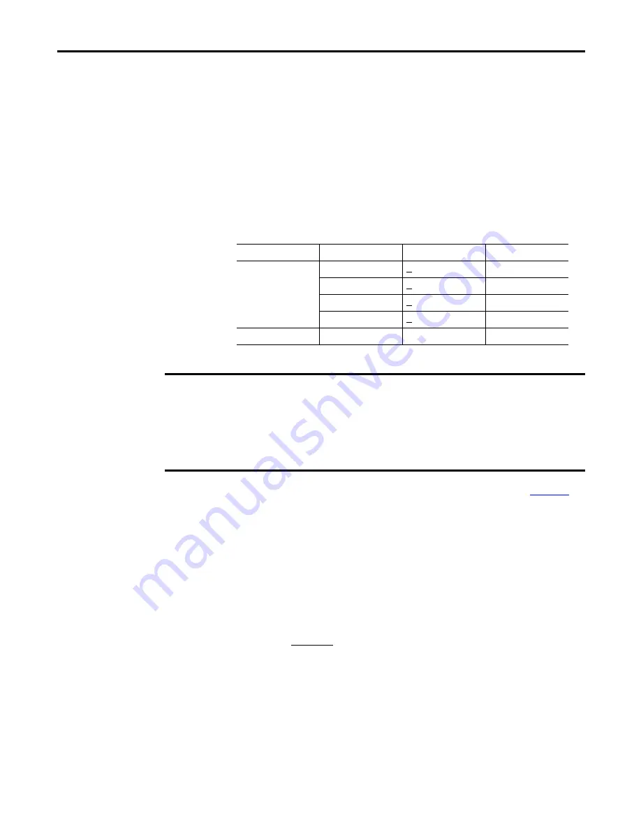
The table lists the input ranges of non-isolated input modules and the
lowest/highest signal available in each range before the module detects an
underrange/overrange condition.
To see where to set the Underrange/Overrange detection values, see
Digital Filter
The digital filter smooths input data noise transients on each input channel. This
value specifies the time constant for a digital first order lag filter on the input. It is
specified in units of milliseconds. A value of 0 disables the filter.
The digital filter equation is a classic first order lag equation.
Table 15 - Low and High Signal Limits on Temperature-measuring Input Modules
Input Type
Available Range
Underrange Threshold
Overrange Threshold
RTD
0…500
Ω
< 0.00
Ω
510.00
Ω
0…1000
Ω
< 0.00
Ω
1020.00
Ω
0…2000
Ω
< 0.00
Ω
2040.00
Ω
0…4000
Ω
< 0.00
Ω
4080.00
Ω
Thermocouple
-100…100 mV
- 101.00 mV
101.00 mV
IMPORTANT
Be aware that the Disable All Alarms feature, does not disable the underrange/overrange
detection feature. The Disable All Alarms feature disables all alarms on the module.
The underrange/overrange detection feature is not an alarm. It is an indicator that channel data
has gone beyond the absolute maximum or minimum, respectively, for the channel’s chosen
range but does not trigger an alarm.
To disable the underrange/overrange detection feature, you must disable the channel.
Y
n
= Y
n
-1
+
X
n
- Y
n
-1
[
∆
t
]
∆
t
+ TA
Y
n
= Present output, filtered peak voltage (PV)‘
Y
n
-1
= Previous output, filtered PV
∆
t
= Module channel update time (seconds)
TA = Digital filter time constant (seconds)
X
n
= Present input, unfiltered PV


