Allen-Bradley 1203-SSS User Manual Download Page 18

3-6

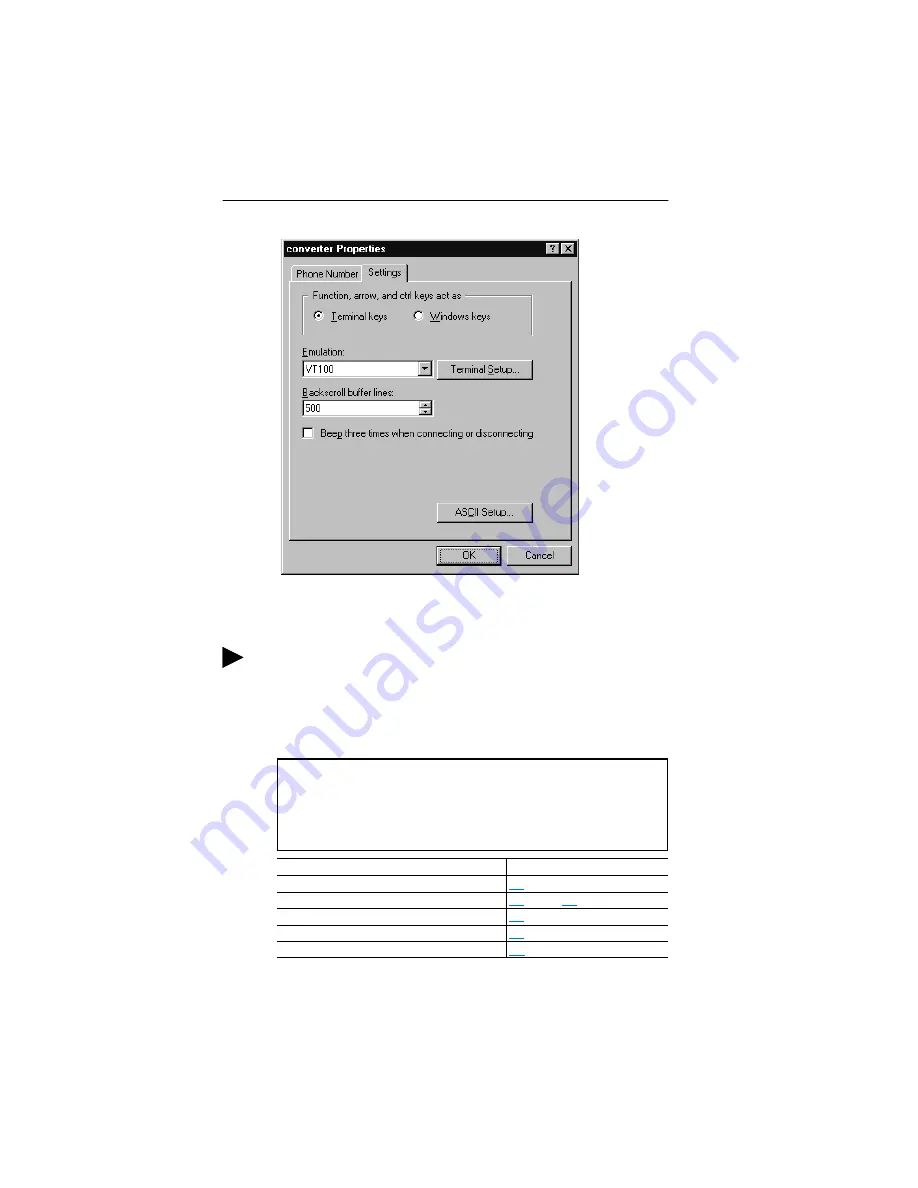
Configuring the Serial Converter

Figure 3.5   Properties Dialog Box

14. Click OK to display the HyperTerminal workspace.

15. Press the Enter key until the main menu appears.

Figure 3.6   Main Menu

S005

TIP:  Select File > Save to save the HyperTerminal configuration that 
you just created. In future connections, you can select the saved 
configuration and quickly connect to the converter.

What do you want to do?

Page

Set up terminal emulation software

3-3

Edit the DF1 address, serial port rate, or fault action

3-7

 through 

3-9

View the event queue

4-3

View DF1 data

4-4

Update the firmware

C-1

Main Menu - Enter Number for Selection

1> Display Setup Parameters

2> Display Event Queue

3> Update FLASH Program

Summary of Contents for 1203-SSS

Page 1: ...Smart Self powered Serial Converter Cat No 1203 SSS Series B FRN 2 xxx Allen Bradley User Manual Allen Bradley...

Page 2: ...delines for the Application Installation and Maintenance of Solid State Control available from your local Allen Bradley office or online at http www ab com manuals gi describes some important differen...

Page 3: ...xxx represents the parameter number The represents the parameter name Menu commands are shown in bold type face and follow the format Menu Command For example if you read Select File Open you should...

Page 4: ...ition Rockwell Automation representatives are in every major country in the world Local Support Contact your local Rockwell Automation representative for Sales and order support Technical training War...

Page 5: ...r 1 3 Required Equipment and Tools 1 4 Safety Precautions 1 4 Quick Start 1 4 Chapter 2 Installing the Serial Converter Objectives 2 1 Selecting Cables 2 1 Installing the Serial Converter 2 2 Removing...

Page 6: ...g DF1 Data 4 4 Troubleshooting Potential Communications Problems 4 5 Appendix A Specifications Objectives A 1 Converter Specifications A 1 Appendix B Serial Converter Parameters Objectives B 1 Paramet...

Page 7: ...Number Device Description 1 Product Refer to Compatible SCANport Products in this chapter 2 SCANport Cable This connection supports the communications with a SCANport product and provides power to th...

Page 8: ...manual is for Firmware releases 2 xxx Compatible SCANport Products The serial converter can be used with Allen Bradley SCANport products including the following Equipment Supplied with the Converter W...

Page 9: ...mputer Refer to Chapter 4 5 RS 232 Serial Port Locking low profile connector The 1203 SFC serial cable is plugged into this connector 6 1202 C10 SCANport Cable SCANport cable 1 m with male to male con...

Page 10: ...ct using a serial converter Failure to comply may result in injury and or equipment damage ATTENTION Risk of injury or equipment damage exists If the serial converter is transmitting control I O to th...

Page 11: ...ground wire should be connected to the serial cable shield at the shell of the 9 pin sub miniature D connector Topic Page Selecting Cables 2 1 Installing the Serial Converter 2 2 Removing the Serial...

Page 12: ...green to indicate that the converter is properly installed and receiving power If it does not illuminate refer to Chapter 4 Removing the Serial Converter 1 Disconnect the SCANport cable from the produ...

Page 13: ...the converter and edit its parameters Topic Page Factory Default Settings 3 1 Accessing Parameters in a Converter 3 1 Using DriveExplorer 3 2 Using Terminal Emulation Software 3 3 Key Strokes for Term...

Page 14: ...lete a step refer to the online help select Help Help Topics or the DriveExplorer User Manual Publication 9303 5 0 which is included on the CD Figure 3 1 DriveExplorer Step Action 1 Select Explore Con...

Page 15: ...st Windows operating system Important The following instructions use screen captures from Windows 95 HyperTerminal If you are using Windows NT or Windows 98 HyperTerminal screens may differ To use Hyp...

Page 16: ...e 3 3 Connection Dialog Box 4 In the Name box type any name e g converter and then select any icon in the Icon box 5 Click OK to display the Phone Number dialog box 6 In the Connect Using box select t...

Page 17: ...select that value in the Bits per second box Figure 3 4 Properties Dialog Box 9 Click OK A blank HyperTerminal workspace appears 10 Select File Properties to display the Properties dialog box 11 Click...

Page 18: ...onfiguration that you just created In future connections you can select the saved configuration and quickly connect to the converter What do you want to do Page Set up terminal emulation software 3 3...

Page 19: ...dress Parameter 3 Press or to scroll to the desired value and then press Enter 4 Reset the converter Refer to Resetting the Converter in this chapter Key Description 0 9 In the main menu keys 1 3 sele...

Page 20: ...al port rate To set the serial port rate 1 In the main menu Figure 3 6 press 1 to display the parameters 2 Press or to scroll to P3 Serial Port Rate Figure 3 8 Serial Port Rate Parameter 3 Press or to...

Page 21: ...The SCANport product is sent 0 for output data after a communications disruption This does not command a stop Hold last state The SCANport product continues in its present state after a communications...

Page 22: ...scroll to Enable and then press Enter to reset the converter ATTENTION Risk of injury or equipment damage exists If the serial converter is transmitting control I O to the SCANport product indicated b...

Page 23: ...e 4 1 Figure 4 1 LEDs on the Serial Converter Topic Page Understanding the LEDs 4 1 Viewing and Clearing the Event Queue 4 3 Viewing and Clearing DF1 Data 4 4 Troubleshooting Potential Communications...

Page 24: ...n the SCANport product Flashing Red The SCANport product has not acknowledged the converter Verify that cables are securely connected Solid Red Link Failure The SCANport product does not allow port co...

Page 25: ...his because it did not receive a response to a message within the time out interval No SCANport Ping The converter issued this because no SCANport pings were detected within a 2 second period This eve...

Page 26: ...n menu in the converter firmware Refer to Accessing Parameters in a Converter in Chapter 3 To view DF1 data 1 In the main menu press 1 to select Display Setup Parameters 2 Press or to scroll through t...

Page 27: ...press Enter In DriveExplorer parameter values are not updated Reset the serial port rate in the software Instructions are included here for resetting the serial port rate in HyperTerminal and DriveExp...

Page 28: ...4 6 Troubleshooting the Serial Converter Notes...

Page 29: ...ative Humidity 5 to 95 non condensing Vibration Operating Non Operating 2 5G 5Hz 2KHz 5 G 5Hz 2KHz Shock Operating Non Operating 30 G peak acceleration 11 1 ms pulse width 50 G peak acceleration 11 1...

Page 30: ...A 2 Specifications Notes...

Page 31: ...alues Fault Zero Data Hold Last Reset Required Yes 5 Reset Adapter If this parameter is set to enable the adapter is reset If it is set to Set Defaults the parameters in the adapter are reset to their...

Page 32: ...ad Only Minimum 0 Maximum 65535 Reset Required No 12 NAKs Received Displays the number of NAK characters received by the converter 2 Default 0 Type Read Only Minimum 0 Maximum 65535 Reset Required No...

Page 33: ...g HyperTerminal Note parameter values Updates may reset parameters to defaults Close all programs except the terminal emulation program that you are using to FLASH the converter Disable the screen sa...

Page 34: ...Box To update the FLASH memory you need a terminal program capable of downloading a binary file using the XMODEM protocol and a FLASH update file from Rockwell Automation When you press Y to signal th...

Page 35: ...com Then perform the FLASH procedure The X Transfer Send for dialog box appears but the FLASH file is not transferred Verify that you have selected the Xmodem protocol in the Send file dialog box Ver...

Page 36: ...C 4 FLASH Updates Notes...

Page 37: ...1 data transparency and F1 two way simultaneous transmission with embedded responses DriveExplorer An easy to use software application designed for Microsoft Windows 95 Windows 98 Windows NT 4 0 or gr...

Page 38: ...ct A device that uses the SCANport communications interface to communicate with one or more peripheral devices For example a motor drive such as a 1336 PLUS II is a SCANport product In this manual a S...

Page 39: ...gs 3 1 DF1 definition G 1 setting an address 3 7 viewing data 4 4 Diamond LED 4 2 dimensions A 1 documentation P 1 DriveExplorer definition G 1 documentation P 1 free lite version G 1 using 1 1 3 2 dr...

Page 40: ...t numbers 1 3 parts 1 3 power consumption A 1 power cycle 3 10 products see SCANport products protocol A 1 Q quick start 1 4 R regulatory compliance A 1 related documentation P 1 removing a serial con...

Page 41: ...s A 1 T technical support P 2 terminal emulation software 3 1 3 3 tools see equipment troubleshooting 4 1 TX LED 4 2 U update see FLASH update V viewing DF1 data 4 4 VT100 compatible terminal 3 1 W we...

Page 42: ...Index 4 Notes...

Page 43: ...radley DriveExplorer DriveTools32 SCANport and SMC Dialog Plus are trademarks of Rockwell Automation Windows Windows CE Windows NT and Microsoft are either registered trademarks or trademarks of Micro...

Page 44: ...Publication 1203 5 15 August 1999 PN 193416 01 1999 Rockwell International Corporation Printed in the U S A...

Reviews: