background image

ALINCO, INC.

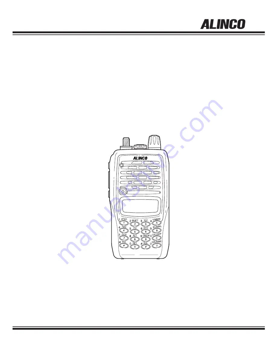
VHF FM TRANSCEIVER

DJ-V17T/E/R/TFH

Instruction Manual

Thank you for purchasing your new Alinco transceiver.
This instruction manual contains important safety and
operating instructions.  Please read this manual
carefully before using the product and keep it for future
reference.

Summary of Contents for DJ-V17E

Page 1: ...FH Instruction Manual Thank you for purchasing your new Alinco transceiver This instruction manual contains important safety and operating instructions Please read this manual carefully before using t...

Page 2: ...the separation between the equipment and receiver Connect the equipment into an outlet on a circuit different from that to which the receiver is connected Consult the dealer or an experienced radio TV...

Page 3: ...o com usa html DJ V17E VHF FM Transceiver 144 000 145 995MHz CE 0336 This device is authorized for use in all EU and EFTA member states An operator s license is required for this device Copyright All...

Page 4: ...amage your skin Rinse with plenty of cold water if the liquid contacted your skin j Keep the radio out of the reach of children a Do not use this product in close proximity to other electronic devices...

Page 5: ...o not place the product in a container carrying conductive materials such as water or metal in close proximity to the product A short circuit to the product may result in electric shock fire and or ma...

Page 6: ...f this product for service and assistance m For your safety turn off then remove all related AC lines to the product and its accessories from the wall outlet if a thunderstorm is likely a Do not handl...

Page 7: ...able DC cable battery cigar cable charger adapter etc from the product when the product is not in use for extended period of time or in case of maintenance a Do not connect devices other than specifie...

Page 8: ......

Page 9: ...gned to operate to your satisfaction for many years under normal use PLEASE READ THIS MANUAL COMPLETELY TO LEARN ALL THE FUNCTIONS THE PRODUCT OFFERS WE MADE EVERY ATTEMPT TO WRITE THIS MANUAL TO BE A...

Page 10: ...perations of Keys and Ports 19 3 2 Keypad 21 3 3 Display LCD 22 4 Basic Operation 23 4 1 Turning On the Power 23 4 2 Adjusting the Audio Output Volume 23 4 3 Adjusting the Squelch 23 4 4 Setting the F...

Page 11: ...eration 34 5 6 Time Out Timer TOT 35 5 6 1 Setting TOT 35 5 6 2 TOT Operation 35 5 7 Lamp 35 6 Selective Calling 36 Selective Calling Operations 36 6 1 Tone Squelch TSQ 36 6 1 1 Setting the Tone Squel...

Page 12: ...TOT Penalty Time 47 8 3 8 Menu 8 DTMF WAIT Time 47 8 3 9 Menu 9 DTMF Burst Pause Time 47 8 3 10 Menu 10 DTMF First Digit Burst Time 48 8 3 11 Menu 11 Battery Charge Function 48 8 3 12 Menu 12 Battery...

Page 13: ...Repeater Access function Refresh function for rechargeable battery reconditioning Cable Cloning The factory guarantees this grade for 1 year when all the jack covers are properly and securely closed...

Page 14: ...antenna counter clockwise to disconnect the antenna 2 1 2 Hand Strap Attach the hand strap as shown There are two ways to attach it 2 1 3 Belt Clip Attaching the Belt Clip 1 Put the belt clip on the...

Page 15: ...pack in the water as this can be dangerous Never short circuit the battery pack terminals as this can cause damage to the equipment or lead to heating of the battery which may cause burns Unnecessary...

Page 16: ...e 48 Select CHG ON Battery Type Setting page 49 Select BATT NI 4 After completing the settings a flashing appears on the display Make sure the icon is flashing then turn off the unit It takes about 10...

Page 17: ...tive enclosure bags or handkerchief made only of non conductive material Do protect by spreading a non conductive sheet on a flat surface NOTE Please read the general safety instructions included in t...

Page 18: ...in usable condition Battery level is low Replace or charge the pack Caution This dry cell case isn t water proof Be extra cautious to the polarity of the cells Misplacing cells may result in leak fire...

Page 19: ...Rotating the dial while pressing the FUNC key increases or decreases the frequency in 1MHz order For an optional speaker Mic connection Securely close the cover for water proof while the accessory is...

Page 20: ...s press the FUNC key continuously for about 2 seconds Press the PTT key to transmit release to receive When the MONI key is pressed the squelch unmutes regardless of the TSQ DCS setting Pressing the M...

Page 21: ...fset frequency setting page 26 Time Out Timer setting page 35 Tone Encode Tone Squelch setting page 36 Hi Low power setting page 30 Auto Power Off setting page 34 DCS digital code squelch setting page...

Page 22: ...ess function is activated Appears when Auto Power Off function is activated Indicates battery level The black icon flashes when the battery charge function is on Displayed when in the Memory mode Disp...

Page 23: ...ss any key except for the MONI key or just leave it for 5 seconds to automatically complete the setting Squelch is a function that eliminates the noise when no signals are being received There are 10...

Page 24: ...Press the FUNC key and while is displayed on the screen rotate the dial to increase or decrease depending on the direction of rotation the frequency by 1MHz order Entry from the Keypad Use the numeric...

Page 25: ...the new setting DOWN STP 5 STP 10 STP 12 5 STP 15 STP 20 STP 25 STP 30 unit kHz UP Tuning step 5 0kHz 10 0kHz 12 5kHz 15 0kHz 20kHz 25kHz 30kHz Entry completion digit 1kHz 10kHz 10kHz 10kHz 10kHz 10kH...

Page 26: ...ey and rotate the dial to increase or decrease the frequency in 1MHz steps 4 Press any key except for the MONI or FUNC key to complete setting This mode allows recalling and operating the preprogramme...

Page 27: ...operating frequency by just 2 key touches Please set the parameters to be applied to the Repeater Access function here 1 Enter the Memory mode by pressing the key if necessary 2 Rotate the dial to se...

Page 28: ...el lockout BCLO Transmission power H L Battery save setting Clock Shift setting Alphanumeric channel tag Attenata Level This mode is used to recall a most frequently used memory channel stored in MC c...

Page 29: ...the audio is intermittently cut off by the squelch press the MONI key As long as this key is pressed the squelch including TSQ DCS unmutes making the audio easier to hear The squelch is unmuted while...

Page 30: ...utput When the low power output is selected is displayed on the LCD nothing is displayed when the high power is selected The initial setting is low power The Power meter display is when transmitting a...

Page 31: ...ode 2 Press the key to start scanning The unit scans in accordance with the order of one step 3 Rotate the dial clockwise counter clockwise to change the scan direction VFO scan scans the entire frequ...

Page 32: ...he same to quit When the Keylock is on the is displayed on the LCD When the Keylock is on other than the following all operations are blocked PTT LAMP MONI VOL SQL Tone burst POWER ON OFF DTMF tone Th...

Page 33: ...cter The previous character will stop flashing 6 Repeat the same sequence as necessary Press the key during setting to delete all characters 7 Press any key except MONI to complete the setting 5 4 2 U...

Page 34: ...uto Power Off function is set Repeat the same to turn it off The initial setting for the APO function is off 5 5 2 APO Operation After having activated the APO and about 30 minutes elapse without any...

Page 35: ...be activated Refer to page 47 for TOT penalty time setting Press the FUNC key and while is displayed on the LCD press the MONI key to illuminate the display and DTMF keypad The backlight automaticall...

Page 36: ...CD press the key to display the current TSQ settings Each time the key is pressed the display shows When only is displayed the unit encodes the CTSS tone When is displayed the unit encodes and decodes...

Page 37: ...tone The decode tone is set automatically to the same tone To differentiate the decode tone select another tone in status 6 1 4 Tone Squelch Operation The squelch unmutes only when the signal with the...

Page 38: ...the unit receives the matching code 6 2 5 DET Mode in DCS Operation DET Setting If the DET mode in DCS operation is preferred while in the DCS Code Setting mode and DCS OF is displayed rotate the dia...

Page 39: ...station A with its corresponding DCS is gone you may still hear station B even his DCS code is different from A although he can t open your DCS squelch by his signal alone To Manually Transmit DTMF To...

Page 40: ...5 123456 234567 345678 456789 To set a pause instead of a tone press the FUNC key and while is displayed press the key is displayed for a pause The pausing time is approx 1 second Press the FUNC key a...

Page 41: ...Press the key The last DTMF tones either the auto dialer code or a manually input DTMF code is automatically generated from the speaker The unit doesn t transmit the tones in this operation 3 To tran...

Page 42: ...the or MONI key to turn off this function Observe that disappears from the display Repeating improper recharge of the Ni MH battery pack may cause so called the memory effect that the battery holds le...

Page 43: ...ers programmed in the VFO memory CALL modes Repeater Access 7 3 Caution The time to refresh totally depends on the remaining charge of the battery pack To discharge the fully charged EBP 65 may take u...

Page 44: ...ny key other than the MONI key and FUNC key to complete the settings The last operated menu will be selected the next time you enter the Set mode Entering the Set Mode 8 2 01 BS ON Battery Save ON OFF...

Page 45: ...r packet operation The display remain unchanged even the BS function is in the OFF cycle 8 3 2 Menu 2 Timer Busy Scan Setting Select the scan resume condition in this menu page 31 1 TIMER is displayed...

Page 46: ...n restricts the PTT transmit operation 1 BCL OF is displayed on the LCD 2 Rotate the dial to select the Busy Channel Lockout setting on and off When Busy Channel Lockout is set to on transmission is p...

Page 47: ...lay the time to start transmitting the DTMF tones in Auto Dialer operation The initial setting is 100ms 1 DWT 01 is displayed on the LCD 2 Rotate the dial to change the DTMF wait time setting 8 3 9 Me...

Page 48: ...this function The factory setting is OFF 1 CHG OF is displayed on the LCD 2 Rotate the dial to select the battery charge setting on and off 3 Please be sure to read Battery Type Setting page 49 to cor...

Page 49: ...kaline dry cells BATT AL Cut out the Set Mode Function List below for use as a quick reference BS ON Battery Save TIMER Timer Busy scan BEP ON Beep sound 1750 Tone Burst Frequency SFT OF CPU Clock Fre...

Page 50: ...g the cable Connect the Microphone Speaker jack on the Master unit with the Slave unit using an optional clone cable EDS 11 as shown below then turn on both units 9 1 2 Master Slave Units Press the PT...

Page 51: ...he data transfer starts 2 After the transfer is completed PASS is displayed 3 After the cloning is done turn off the unit by pressing the key and remove the cable Repeat the same sequence to clone mor...

Page 52: ...5 plug on the EDS 10 as shown below Input level adjustment The unit doesn t have microphone and speaker level adjustment circuit Adjust their level on the TNC side Output level adjustment Use the audi...

Page 53: ...ery pack connection Battery is exhausted You are releasing the key too quickly Volume too low Squelch level too high Tone squelch is on DCS is on You are pressing the PTT key and transmitting CPU erro...

Page 54: ...uture reference VFO Frequency CALL Frequency Memory Channel Channel Step Shift Offset Frequency Tone Setting Tone Frequency DCS Setting DCS Code Transmitter Output Auto Dialer Code Keylock Time Out Ti...

Page 55: ...Wall Charger 230V EDC 148 Wall Charger 230V U K Socket EDH 34 Dry Cell Case EDS 10 Microphone Speaker Cable EDS 11 Clone Cable EME 6 Earphone EME 12 Headset with VOX EME 13 Earphone and MIC with VOX E...

Page 56: ...ry packs aren t fully charged when shipped Please charge the pack completely before use Available Battery Packs for DJ V17 EBP 63 Li ion Battery Pack DC 7 4V 1100mAh EBP 64 Li ion Battery Pack DC 7 4V...

Page 57: ...on cable insulation sheet 2 screws connective stay 1 Connect the AC adapter plug to the DC IN jack on the back of the basket The design of the AC adapter may vary depending on the models 2 Connect the...

Page 58: ...56 remove the battery pack from the basket The red indicator stays turned on as long as the pack is mounted on the basket regardless of the charging status Specifications The charging time may vary d...

Page 59: ...o the DC IN jack on the back of the basket The design of the AC adapter may vary depending on the models 2 Connect the adapter to an outlet 3 Press the sides of the adjustment plate and attach it to t...

Page 60: ...depending on the condition of the battery pack and the temperature of the environment Input Voltage Operating Temperature Range Charging Current DC 12 0V 700mA 0 C 40 C 32 F 104 F 600mA Battery Capaci...

Page 61: ...cable the red cable to the positive and the black cable to the negative terminals The additional basket can be connected up to 5 in the same way 3 Connect the ends of the DC cable to the terminals of...

Page 62: ...10 Maintenance and Reference 10 62 5 Connect the other ends of the DC cable to the output terminals of the power supply Be mindful to the polarities of the terminals DC cable Power supply...

Page 63: ...unction memory Ant impedance 50 unbalanced Frequency stability 5ppm Mic impedance 2k Supply voltage DC 7 0 16 0V EXT DC IN Current consumption 1 4A typical Transmit high at 5W 250mA typical Receive at...

Page 64: ...dulation Variable reactance Spurious emission 60dB or less Max deviation 5kHz Mic impedance 2k Receiver System Double conversion super heterodyne Sensitivity 14 0dB 0 2 V or less Intermediate frequenc...

Page 65: ...Head Office Shin Dai building 9th Floor 2 6 1 Chome Dojimahama Kita ku Osaka 530 0004 JAPAN Phone 81 6 4797 2136 Fax 81 6 4797 2157 E mail export alinco co jp Printed in Japan Copyright Alinco Inc PS...

Reviews: