background image

No 1249 E Febr. -05.

S

SC

CA

AN

ND

DO

O 6

65

50

0  M

Mo

od

du

ulla

ar

r  S

Sy

ys

stte

em

m

Pictures are illustrative only and do not necessarily show the configuration of products on the market at the given point in time. Products must be used in conformity with safe 

practice and applicable statues, regulations, codes and ordinances. Specifications of products and equipment shown herein are subject to change without notice.

Printed in Sweden

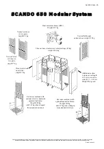
2.8 m car base structure incl. safety railings (85 kg),

weight 1500 kg 

Exit door combined with

optional  electric / hydraulic

operated load ramp. 

Weight 280 kg.

Add 147 kg when changed

from standard exit door.

Exit door combined with 

optional manual load ramp. 

Weight 250 kg.

Add 117 kg when changed

from standard exit door.

Closed, solid wall
on exit side,
weight 55 kg

Vertical full height 

entrance door, weight 155 kg

Dual motor machinery (DOL)

Weight  495 kg

Vertical exit door

in two parts,

weight 133 kg

Vertical ”slim”

exit door in

two parts,

weight 77 kg

Additional section
to increase car length
0.35 m in one or two
sides (0.35 + 0.35 m).
Weight 90 kg each.

Summary of Contents for Scando 650 DOL

Page 1: ...01 30 If the bottom right corner of this book is cut the book is only valid for illustrative use This manual is only applicable if the manufacturing number indicated below corresponds to the manufacturing number stamped on the identification sign of the equipment Where there is a conflict contact your ALIMAK representative ...

Page 2: ...arily show the design of the products on the market at any given point in time The products must be used in conformity with applicable practice and safety regulations Specifications of the products and equipment presented herein are subject to change without notice ...

Page 3: ... DATA SPECIFICATIONS IMPORTANT SAFETY INSTRUCTIONS OPERATING INSTRUCTIONS SERVICE AND MAINTENANCE ELECTRIC TROUBLESHOOTING FOUNDATION HOIST MAST PREPARATIONS BEFORE INSTALLATION See Operator s Manual for chapter C D E and F Copyright Alimak AB 2004 All rights reserved ...

Page 4: ......

Page 5: ...enclosure Hoist mast Car Drive unit Cable guiding device Control systems Landing equipment Safety equipment Optional equipment The purchaser s user s own protective measures Load signs A 1 A 1 A 2 A 2 A 3 A 4 A 6 A 9 A 11 A 12 A 14 A 16 A 18 A 24 A 25 ALIMAK 34738 1 01 A0 ...

Page 6: ...2 8 m car base structure 9 2 1 4 3 5 m car base structure 11 5 3 4 ...

Page 7: ...an be set up with single or dual cars The hoist is easily transported by truck to and from the erection site and handled with forklift trucks or jib cranes on the site The SCANDO 650 construction hoist is a part of the SCANDO 650 access system and can be combined with other products i e platforms or materials hoists Regulations The hoist and its mechanical and electrical components are designed an...

Page 8: ...or a precast concrete slab can also be used Base frame The bottom mast section is bolted to the base frame which incorporates 3 buffer positions channels for fork lifting and 2 boltable outriggers to support the enclosure The hoist can be used freestanding bolted to the transportable sheet steel foundation or the concrete slab With an additional buffer support the base frame also incorpo rates a d...

Page 9: ...well as twin car set ups It can also be changed so that another SCANDO 650 modular system hoist platform can operate on the other side of the mast The enclosure is provided with one or two double swing mechanically locked and electrically monitored door s Two entrance doors allow entrance to the car from 2 different directions Doors can be positioned on any of the three sides away from mast ALIMAK...

Page 10: ... bolted to all mast sections The ties are attached to the frames of the mast sections or alt to the rear mast tubes The other end to special brackets attached to the wall The tie length is telescopic adjustable within different intervals The ties can also be inclined from the horizontal Specifications for each particular mast tie can be found in chapter H Mast sections and mast ties are hot dipped...

Page 11: ...tches located on the hoist car Additionally there is a final limit switch activated by separate cams at the top and bottom of the hoistway The final limit switch controls a main contactor which switches off all three phases of the main power supply to the drive motor s A5 Gränsbrytare upp ner Slutgränsbrytare upp ner ALIMAK 34743 1 03 ...

Page 12: ...rically monitored vertical guided entrance and exit doors The doors are modular for flexibility and in the SCANDO 650 access program 4 different car doors are available The lightweight moving door blades consist of aluminium profiles for ease of operation Normally the exit door is manufactured in two parts whereas the entrance door is in one part The entrance door is the one facing the door of the...

Page 13: ...y railing There is also a trapdoor in the roof and a ladder in the car to gain entry to the roof for erection purposes Asymmetrical car configuration The car length on each side of the mast shall be equal if possible The difference may only be one extension section of 0 35 m 1 1 3 4 Although the hoist is asymmetrical it should be considered symmetrical and the longer end dictating the maximum allo...

Page 14: ...ht approx 40 kg 88 lbs exclusive of electric winch Electric winch 3 phase 440V weight 13 kg 29 lbs Movable erection platform optional equipment A manual movable erection platform to ease the mast section assembly and the mast tie installation can be furnished with the SCANDO 650 construction hoists Platform length adapted for different car lengths The platform reach is approximately 2 times its ow...

Page 15: ...ed for an overload sensing system OSS The safety device is completely independent from the drive unit and installed inside the car with two pinions engaging the rack The device is actuated by a centrifugal weight and stops the hoist when the normal rated speed is exceeded FC vs DOL Frequency controlled electric motors give better softer riding comfort when starting and stopping better stopping acc...

Page 16: ...A10 ...

Page 17: ...le are fixed firmly to the mast from ground level to a junction box in the mast halfway to the mast top The trailing power cable and the control cable from the junction box to the cable brackets on the car are tensioned by cable trollies The cable trollies travel on a separate guide rail attached close to the mast from ground level to a point halfway to the mast top Differential expansion contract...

Page 18: ...w developed to work without any landing cams The position of the hoist is determined by counting impulses generated by the pulse encoder attached to the gear box The machine can be operated from inside the hoist and if chosen also from the landings by using Up Down and Stop Next Landing push buttons By pressing a button for up or down the hoist starts travelling in the chosen direction When the ho...

Page 19: ...y destination push buttons or a keypad and if chosen also called from the landings Each landing is provided with two Call buttons one for Up and Down resp The actual position and the hoist destination is shown on displays inside the car On these displays a fault indica tion is given ALIMAK 34751 1 01 A13 Push button panels at landings a 143 a 143 ...

Page 20: ...is connected to the control system of the hoist stop circuit The landing el equipment consists of a stainless steel box with necessary control push buttons for calling the hoist Connection cable as well as limit switch or electromechanical locks for monitoring of the landing door or alternatively the landing gate The equipment is provided with a 6 pole socket outlet and plug on the connection cabl...

Page 21: ... protection class IP 54 or higher A15 ALIMAK 34753 1 03 Vertical scaffold pipes parallel to the mast from the ground to the mast top attached outside the ground enclosure Accessories for landing run offs On site built landing run off ...

Page 22: ...ending hoist beyond its normal limit of travel Safety details on machinery plate On the machinery and safety device plates heels keep the pinion of the machinery and safety device constantly engaged with the rack on the hoist mast in case a counter roller or a guide roller on the cage comes off Safety hooks To prevent the hoist from climbing off the mast during erection or dismantling or to preven...

Page 23: ...gaged with the rack on the hoist mast When the centrifugal weight activates the brake cone is screwed in against a brake lining inside the safety housing The hoist is brought to a smooth stop and simultaneously the power to the drive motor is cut off In case of guide roller failure there are separate safety hooks provided which prevent the pinion of the safety device from disengagement with the ra...

Page 24: ...ugal brake incorporated into the drive machinery will maintain a constant speed preventing the car from reaching governor tripping speed and thereby activating the safety device ALIMAK 34756 1 01 A18 Coupling half on brake motor Brake lining Axially movable lock ring to lock release the centrifugal brake hub ...

Page 25: ...cting the machinery to the car structure When the rated load is exceeded the control circuit will be switched off to prevent the use of the hoist At the same time a red LED lights Fault code F4 will be displayed where ALC floor call selecting device occurs ALIMAK 34757 1 01 A19 Indication light Overload in car Signals from the load cells are transferred to the OSD 4 amplifier located in M panel Ge...

Page 26: ... a plastic membrane below the gravel Set the sheet steel plate onto the prepared gravel bed at its proper location Using a spirit level to locate the highest level guide pin From the highest level guide pin use shim washers or pair of slotted shims to level remaining pins Using slotted shims in pairs are more desireable than shim washers as adjustments can be made after the base is installed allow...

Page 27: ...or the mast sections corner tubes in the base frame Assemble and tighten the bolts for the attachment of the mast s base frame to the steel sheet foundation with bolts intended for this purpose Lift lower and assemble the drive unit located on a mast section Connect the machinery to the hoist s power and control circuits Note Hoist components such as ground enclosure not shown for clarity ...

Page 28: ... in length Two pair of tube couplers are used on each mast section Car length Payload Freestandig During in operation erection Hoist installed on 2 pce steel sheet foundation 3 2 m 10 6 2000 kg 4400 lbs 22 5 meter zone C 3 9 m 12 9 1 2 4 6 m 15 1 A22 ALIMAK 34760 1 01 Car length Car payload Freestandig in opeartion During erection capacity Single car Dual cars Single car Hoist installed on 1 pce s...

Page 29: ...nsions 3 5 x 2 5 meter 11 5 x 8 5 Concrete volume 15 m3 20 cu yds Please contact Alimak Calculation Department for advice It may be desirable to connect three mast towers to each other This is a preferable method to achieve greater height to increase the distance to the top tie On the Eiffel Tower Project in Paris 55 meter 180 ft was achieved By increasing the number of attached towers the overall...

Page 30: ...e measures Protection at the landings It is recommended that overhead protection is furnished at landing entrances to protect against falling objects Scaffolds and other gangways close to the hoistway Scaffolds and other gangways and platforms close to the hoist way shall be provided with enclosures according to local regulations Illumination of landings Adequate site lighting shall be provided to...

Page 31: ...n Click here Acrobat PDF Note It is possible to copy text and paste into your own word processing program on your computer Sign inside the car showing specifications for the particular installation It is possible to write erase the sign inside the car showing specifications for the particular installation The sign must be filled in and signed by a person responsible for the entire hoist installati...

Page 32: ......

Page 33: ... 3 9 m B 2 Car length 3 5 3 9 m B 3 Car extended length 3 9 4 6 m B 4 Technical data sheet B 6 Dimensions B 7 Tie distance and overhang B 14 Lubrication and lubrication quantities B 14 Electric circuit diagram B 14 Location of landing door gate B 15 Tightening torque B 17 ALIMAK 34764 1 01 B0 ...

Page 34: ...2300 kg 2400 kg 2000 2200 kg 1000 1700 kg 2800 3200 kg 1800 2400 kg or 24 pers or 24 pers or 24 pers or 24 pers or 24 pers or 24 pers No 1202 No 1204 No 1206 No 1210 No 1212 No 1214 1900 2200 kg 2200 kg 1900 2000 kg 900 1700 kg 2700 3200 kg 1700 2300 kg or 22 24 pers or 24 pers or 24 pers or 24 pers or 24 pers or 24 pers No 1202 No 1204 No 1206 No 1210 No 1212 No 1214 Product range car length 2 8 ...

Page 35: ... 22 24 pers or 24 pers or 22 pers or 24 pers or 29 pers or 29 pers No 1203 No 1205 No 1208 No 1211 No 1213 No 1215 1800 2000 kg 2000 kg 1800 kg 800 1600 kg 2600 3200 kg 1600 2200 kg or 22 24 pers or 24 pers or 22 pers or 24 pers or 29 pers or 29 pers No 1203 No 1205 No 1208 No 1211 No 1213 No 1215 1700 1900 kg 1900 kg 1700 kg 800 1500 kg 2500 3200 kg 1500 2100 kg or 21 pers or 24 pers or 20 pers o...

Page 36: ...300 kg or 22 24 pers or 24 pers or 22 pers or 24 pers or 29 pers or 28 pers No 1249 No 1250 No 1254 No 1255 No 1218 No 1220 1700 200 kg 2000 kg 1800 kg 1300 1500 kg 2600 3200 kg 1600 2200 kg or 21 pers or 24 pers or 20 pers or 24 pers or 29 pers or 27 pers No 1249 No 1250 No 1254 No 1255 No 1218 No 1220 Product range car length 3 5 3 9 m Car configuration car length 3 5 m car length 3 9 m car leng...

Page 37: ... NA NA NA NA 2500 3000 kg 1500 2100 kg or 29 pers or 27 pers No 1219 No 1221 NA NA NA NA 2500 3000 kg 1500 2100 kg or 29 pers or 27 pers No 1219 No 1221 NA NA NA NA 2400 3000 kg 1400 2000 kg or 29 pers or 26 pers No 1219 No 1221 Additional section to increase car length 0 35 m on one or two sides Closed solid wall on exit side car length 3 9 m car length 4 6 m car length 4 6 m car length 4 6 m car...

Page 38: ...B5 ...

Page 39: ...SCANDO 650 FC 35 39 ext 0 7 m s No 1208 SCANDO 650 FC 35 39 0 7 m s No 1254 SCANDO 650 FC 28 32 0 9 m s No 1210 SCANDO 650 FC 35 39 ext 0 9 m s No 1211 SCANDO 650 FC 35 39 0 9 m s No 1255 SCANDO 650 FC 28 32 0 9 m s No 1212 SCANDO 650 FC 35 39 ext 0 9 m s No 1213 SCANDO 650 FC 28 32 1 1 m s No 1214 SCANDO 650 FC 35 39 ext 1 1 m s No 1215 SCANDO 650 FC 35 39 0 9 m s No 1218 SCANDO 650 FC 39 46 ext ...

Page 40: ...m 307 kg 12 9 1 2 14 1 3 4 677 lbs 4600 mm 5010 mm 331 kg 15 1 16 5 1 4 730 lbs 650 726 2 4 1 2 650 2 1 1 2 764 2 6 Dimensions weight Mast section Length height 1508 mm 4 11 3 8 Weight 115 135 kg 254 298 lbs Mast bolt dimensions 1 UNC galv quality minimum 8 8 or A325 Tightening torque 300 Nm 220 lbf x ft Mast expansion contraction The expansion contraction of the mast is 0 012 mm m and degree C or...

Page 41: ... 13 1 1 2 1152 200 3500 mm 11 5 3 4 car base structure 3 7 m 12 1 3 4 3800 mm 12 5 1 2 eccentric 3 9 m 12 9 1 2 4000 mm 13 1 1 2 1600 kg 3530 lbs 4 25 m 13 11 1 4 4350 mm 14 3 1 4 eccentric 4 6 m 15 1 4700 mm 15 5 exclusive of drive unit and safety railing Allowable concentrated load on floor Concentrated load on a dia 100 mm 4 in roller with length 100 mm is Plywood floor Multi layer built up alu...

Page 42: ...500 mm L4 L5 L4 Height 2500 mm 8 2 1 2 4 11 4 11 4 11 Car length L4 External L5 3 2 m 10 6 3720 mm 12 2 1 2 1845 mm 6 0 3 4 3 9 m 12 9 1 2 4420 mm 14 6 2195 mm 7 2 1 2 4 6 m 15 1 5120 mm 16 9 1 2 2545 mm 8 4 1 4 ALIMAK 34773 1 01 B9 Add additional 0 1 m 4 where accessories for pipe support equipment are added to the ground enclosure Add 0 1 0 1 m if added on both sides ...

Page 43: ... 8 2 1 2 Car length L4 External L5 3 2 m 10 6 3720 mm 12 2 1 2 1845 mm 6 0 3 4 3 9 m 12 9 1 2 4420 mm 14 6 2195 mm 7 2 1 2 4 6 m 15 1 5120 mm 16 9 1 2 2545 mm 8 4 1 4 Add additional 0 1 m 4 where accessories for pipe support equipment are added to the ground enclosure Add 0 1 0 1 m if added on both sides ALIMAK 34774 1 01 B10 4 11 ...

Page 44: ... leaf swing door for landings Scale 1 40 ALIMAK 34775 1 01 B11 Weight 115 kg 254 lbs 1150 5 0 1 4 1530 3 9 1 4 approx 770 mm 2 6 1 4 approx 450 mm 1 5 3 4 Weight 60 kg 132 lbs c c pipe 1750 5 9 1495 4 10 3 4 2300 7 6 1 2 2585 8 5 3 4 1800 5 10 4 1500 4 11 ...

Page 45: ...ation ON slab Scale 1 40 ALIMAK 34776 1 01 Opening G F Over all length E b 75 625 2 0 1 2 Opening G F Over all length E b 76 1100 3 7 1 4 1100 3 7 1 4 338 1 1 1 4 Slab Pipe scaffolding Over all length E F Opening G Weight 4320 14 2 2845 9 4 1560 5 1 1 2 4220 13 10 1 4 2845 9 4 1460 4 9 1 2 4120 13 6 1 4 2845 9 4 1360 4 5 1 2 Weight 69 5 kg 153 lbs ...

Page 46: ...ed Scale 1 40 Width internal 1492 mm 4 10 3 4 Weight 250 kg 550 lbs Vertical sliding exit door with folding ramp el operated EN Approved Scale 1 40 Width internal 1400 mm 4 7 Weight 280 kg 620 lbs 737 2 5 1000 3 3 1 4 1100 3 7 1 4 2027 6 7 3 4 b 78 737 2 5 1000 3 3 1 4 b 77 B13 1100 3 7 1 4 ...

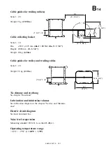
Page 47: ...des for trolley and trailing cables Scale 1 20 Weight 9 5 kg 21 lbs Tie distance and overhang See chapter Hoist mast Lubrication and lubrication volumes See lubrication diagram in the chapter Service and Mainten ance Electric circuit diagram See hoist document box Noise level at operation Measuring standard IEC 651 Less than 85 dB A Operating temperature range 40 C 25 C 140 F 13 F x 7 1 4 187 280 ...

Page 48: ... Door gate Pipe dia Measure L 6 Measure L 7 mm type mm mm mm 3200 mm Alt 1 1695 5 6 3 4 1900 6 2 3 4 10 6 Alt 2 ø 76 3 1695 5 6 3 4 Alt 3 ø 76 3 2640 8 8 Alt 4 2100 3300 6 10 3 4 10 10 see corresp figure 3900 mm Alt 1 ø 76 3 2045 8 8 1 2 2250 7 4 1 2 12 9 1 2 Alt 2 ø 76 3 2045 8 8 1 2 Alt 3 ø 76 3 2990 9 9 3 4 Alt 4 2450 4600 8 0 1 2 15 1 see corresp figure 4600 mm Alt 1 ø 76 3 2395 7 10 1 4 2600 ...

Page 49: ...Outside gate structure L 6 add 95mm 3 3 4 to half car length max 2 50 mm max 7 3 4 200 mm min 1 7 3 4 min 500 min 2 9 1 2 min 850 at speed v 0 7 m s at speed v 0 7 m s 138 fpm C L mast L 6add 1040 mm 3 5 to half car length 265 mm 10 1 2 24 1 L 6 add 500 700 mm to half car length 1 7 3 3 2 3 1 2 100 300 mm 4 11 3 4 Maximum load 150 kg 330 lbs on sill b 83 b 84 b 85 b 86 Alt 3 Exit door with el hydr...

Page 50: ...ly in general except for ALIMAK Mast bolt dim 1 UNC Torque 350 Nm 258 lbf x ft Spanner size 1 1 2 ALIMAK Scaffold clamp Ø 76 mm Torque 150 Nm 110 lbf x ft Spanner size 28 mm ALIMAK Scaffold clamp Ø 76 mm Torque 220 Nm 163 lbf x ft Spanner size 24 or 27 mm ALIMAK 34781 1 01 50 100 B17 ...

Page 51: ...d bolt and nut of strength class 8 8 dry surface ALIMAK 34782 1 01 B18 Dimension Spanner size Torque Nm lbf x ft M 6 M 8 M 10 M 12 M 14 M 16 M 20 M 24 10 mm 13 mm 17 mm 19 mm 22 mm 24 mm 30 mm 36 mm 7 18 35 60 95 146 285 493 10 24 47 81 128 198 386 668 ...

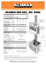
Page 52: ...on exit side weight 55 kg Vertical full height entrance door weight 155 kg Dual motor machinery DOL Weight 495 kg No 1202 E Febr 05 Pictures are illustrative only and do not necessarily show the configuration of products on the market at the given point in time Products must be used in conformity with safe practice and applicable statues regulations codes and ordinances Specifications of products ...

Page 53: ...st section with two racks kg 135 135 135 135 Mast section length mm 1508 1508 1508 1508 TRANSPORT DIMENSIONS Base unit incl ground enclosure Length F m add 0 50 3 m to external length E Width G m 2 55 2 75 2 55 2 55 Maximum height m 3 10 3 10 3 10 3 10 machinery excl S SC CA AN ND DO O 6 65 50 0 D DO OL L 3 32 2 5 50 0H Hz z 3 2 m car with two 1 vertical doors X C22 3 2 m car with three vertical d...

Page 54: ...on exit side weight 55 kg Vertical full height entrance door weight 155 kg Dual motor machinery DOL Weight 495 kg No 1204 E Febr 05 Pictures are illustrative only and do not necessarily show the configuration of products on the market at the given point in time Products must be used in conformity with safe practice and applicable statues regulations codes and ordinances Specifications of products ...

Page 55: ...5 Mast section length mm 1508 1508 1508 1508 TRANSPORT DIMENSIONS Base unit incl ground enclosure Length F m add 0 50 3 m to external length E Width G m 2 55 2 75 2 55 2 55 Maximum height m 3 10 3 10 3 10 3 10 machinery excl S SC CA AN ND DO O 6 65 50 0 D DO OL L 3 32 2 6 60 0 H Hz z 3 2 m car with two 1 vertical doors X C22 3 2 m car with three vertical doors X C23 3 2 m car with one load ramp an...

Page 56: ... 2 8 m car base structure incl safety railings 85 kg weight 1500 kg Exit door combined with optional electric hydraulic operated load ramp Weight 280 kg Add 147 kg when changed from standard exit door Exit door combined with optional manual load ramp Weight 250 kg Add 117 kg when changed from standard exit door Closed solid wall on exit side weight 55 kg Vertical full height entrance door weight 1...

Page 57: ...t section with two racks kg 135 135 135 135 Mast section length mm 1508 1508 1508 1508 TRANSPORT DIMENSIONS Base unit incl ground enclosure Length F m add 0 50 3 m to external length E Width G m 2 55 2 75 2 55 2 55 Maximum height m 3 10 3 10 3 10 3 10 machinery excl S SC CA AN ND DO O 6 65 50 0 D DO OL L 3 39 9 5 50 0 H Hz z Extended 3 9 m car with two 1 vertical doors X C42 Extended 3 9 m car wit...

Page 58: ... 2 8 m car base structure incl safety railings 85 kg weight 1500 kg Exit door combined with optional electric hydraulic operated load ramp Weight 280 kg Add 147 kg when changed from standard exit door Exit door combined with optional manual load ramp Weight 250 kg Add 117 kg when changed from standard exit door Closed solid wall on exit side weight 55 kg Vertical full height entrance door weight 1...

Page 59: ...o racks kg 135 135 135 135 Mast section length mm 1508 1508 1508 1508 TRANSPORT DIMENSIONS Base unit incl ground enclosure Length F m add 0 50 3 m to external length E Width G m 2 55 2 75 2 55 2 55 Maximum height m 3 10 3 10 3 10 3 10 machinery excl S SC CA AN ND DO O 6 65 50 0 D DO OL L 3 32 9 5 50 0H Hz z Extended 3 9 m car with two 1 vertical doors X C42 Extended 3 9 m car with three vertical d...

Page 60: ... 2 8 m car base structure incl safety railings 85 kg weight 1500 kg Exit door combined with optional electric hydraulic operated load ramp Weight 280 kg Add 147 kg when changed from standard exit door Exit door combined with optional manual load ramp Weight 250 kg Add 117 kg when changed from standard exit door Closed solid wall on exit side weight 55 kg Vertical full height entrance door weight 1...

Page 61: ... 135 135 135 135 Mast section length mm 1508 1508 1508 1508 TRANSPORT DIMENSIONS Base unit incl ground enclosure Length F m add 0 50 3 m to external length E Width G m 2 55 2 75 2 55 2 55 Maximum height m 3 10 3 10 3 10 3 10 machinery excl S SC CA AN ND DO O 6 65 50 0 D DO OL L 3 32 9 6 60 0H Hz z Extended 3 9 m car with two 1 vertical doors X C42 Extended 3 9 m car with three vertical doors X C43...

Page 62: ... 2 8 m car base structure incl safety railings 85 kg weight 1500 kg Exit door combined with optional electric hydraulic operated load ramp Weight 280 kg Add 147 kg when changed from standard exit door Exit door combined with optional manual load ramp Weight 250 kg Add 117 kg when changed from standard exit door Closed solid wall on exit side weight 55 kg Vertical full height entrance door weight 1...

Page 63: ...5 Mast section length mm 1508 1508 1508 1508 TRANSPORT DIMENSIONS Base unit incl ground enclosure Length F m add 0 50 3 m to external length E Width G m 2 55 2 75 2 55 2 55 Maximum height m 3 10 3 10 3 10 3 10 machinery excl S SC CA AN ND DO O 6 65 50 0 D DO OL L 3 39 9 6 60 0 H Hz z Extended 3 9 m car with two 1 vertical doors X C42 Extended 3 9 m car with three vertical doors X C43 Extended 3 9 ...

Page 64: ...de weight 55 kg Vertical full height entrance door weight 155 kg Dual motor machinery FC incl VFC panel 45 kW Weight 590 kg No 1206 E Febr 05 Pictures are illustrative only and do not necessarily show the configuration of products on the market at the given point in time Products must be used in conformity with safe practice and applicable statues regulations codes and ordinances Specifications of...

Page 65: ...ction with one rack kg 115 115 115 115 Mast section with two racks kg 135 135 135 135 Mast section length mm 1508 1508 1508 1508 TRANSPORT DIMENSIONS Base unit incl ground enclosure Length F m add 0 50 3 m to external length E Width G m 2 55 2 75 2 55 2 55 Maximum height m 3 10 3 10 3 10 3 10 machinery excl S SC CA AN ND DO O 6 65 50 0 F FC C 3 32 2 3 2 m car with two 1 vertical doors X C22 3 2 m ...

Page 66: ... base structure incl safety railings 85 kg weight 1500 kg Exit door combined with optional electric hydraulic operated load ramp Weight 280 kg Add 147 kg when changed from standard exit door Exit door combined with optional manual load ramp Weight 250 kg Add 117 kg when changed from standard exit door Closed solid wall on exit side weight 55 kg Vertical full height entrance door weight 155 kg Dual...

Page 67: ...ction with one rack kg 115 115 115 115 Mast section with two racks kg 135 135 135 135 Mast section length mm 1508 1508 1508 1508 TRANSPORT DIMENSIONS Base unit incl ground enclosure Length F m add 0 50 3 m to external length E Width G m 2 55 2 75 2 55 2 55 Maximum height m 3 10 3 10 3 10 3 10 machinery excl S SC CA AN ND DO O 6 65 50 0 F FC C 3 39 9 Extended 3 9 m car with two 1 vertical doors X C...

Page 68: ...ons codes and ordinances Specifications of products and equipment shown herein are subject to change without notice Printed in Sweden Exit door combined with optional electric hydraulic operated load ramp Weight 280 kg Add 147 kg when changed from standard exit door Vertical full height entrance door weight 155 kg Vertical exit door in two parts weight 133 kg Vertical slim 1 5 m exit door in two p...

Page 69: ...3050 2 2 2 Mast section with one rack kg 115 115 115 115 Mast section with two racks kg 135 135 135 135 Mast section length mm 1508 1508 1508 1508 TRANSPORT DIMENSIONS Base unit incl ground enclosure Length F m add 0 50 3 m to external length E Width G m 2 55 2 75 2 55 2 55 Maximum height m 3 10 3 10 3 10 3 10 machinery excl S SC CA AN ND DO O 6 65 50 0 F FC C 3 39 9 3 9 m car with two 1 vertical ...

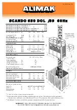
Page 70: ...exit side weight 55 kg Vertical full height entrance door weight 155 kg No 1210 E Febr 05 Pictures are illustrative only and do not necessarily show the configuration of products on the market at the given point in time Products must be used in conformity with safe practice and applicable statues regulations codes and ordinances Specifications of products and equipment shown herein are subject to ...

Page 71: ... weight approx kg 2850 2 2 2 Mast section with one rack kg 115 115 115 115 Mast section with two racks kg 135 135 135 135 Mast section length mm 1508 1508 1508 1508 TRANSPORT DIMENSIONS Base unit incl ground enclosure Length F m add 0 50 3 m to external length E Width G m 2 55 2 75 2 55 2 55 Maximum height m 3 10 3 10 3 10 3 10 machinery excl S SC CA AN ND DO O 6 65 50 0 F FC C 3 32 2 3 2 m car wi...

Page 72: ... base structure incl safety railings 85 kg weight 1500 kg Exit door combined with optional electric hydraulic operated load ramp Weight 280 kg Add 147 kg when changed from standard exit door Exit door combined with optional manual load ramp Weight 250 kg Add 117 kg when changed from standard exit door Closed solid wall on exit side weight 55 kg Vertical full height entrance door weight 155 kg Vert...

Page 73: ...050 2 2 2 Mast section with one rack kg 115 115 115 115 Mast section with two racks kg 135 135 135 135 Mast section length mm 1508 1508 1508 1508 TRANSPORT DIMENSIONS Base unit incl ground enclosure Length F m add 0 50 3 m to external length E Width G m 2 55 2 75 2 55 2 55 Maximum height m 3 10 3 10 3 10 3 10 machinery excl S SC CA AN ND DO O 6 65 50 0 F FC C 3 39 9 Extended 3 9 m car with two 1 v...

Page 74: ...ons codes and ordinances Specifications of products and equipment shown herein are subject to change without notice Printed in Sweden Exit door combined with optional electric hydraulic operated load ramp Weight 280 kg Add 147 kg when changed from standard exit door Vertical full height entrance door weight 155 kg Vertical exit door in two parts weight 133 kg Vertical slim 1 5 m exit door in two p...

Page 75: ...3050 2 2 2 Mast section with one rack kg 115 115 115 115 Mast section with two racks kg 135 135 135 135 Mast section length mm 1508 1508 1508 1508 TRANSPORT DIMENSIONS Base unit incl ground enclosure Length F m add 0 50 3 m to external length E Width G m 2 55 2 75 2 55 2 55 Maximum height m 3 10 3 10 3 10 3 10 machinery excl S SC CA AN ND DO O 6 65 50 0 F FC C 3 39 9 3 9 m car with two 1 vertical ...

Page 76: ...ide weight 55 kg Vertical full height entrance door weight 155 kg No 1212 E Febr 05 Pictures are illustrative only and do not necessarily show the configuration of products on the market at the given point in time Products must be used in conformity with safe practice and applicable statues regulations codes and ordinances Specifications of products and equipment shown herein are subject to change...

Page 77: ...n request WEIGHTS Base unit weight approx kg 3250 2 2 2 Mast section with one rack kg 115 115 115 115 Mast section with two racks kg 135 135 135 135 Mast section length mm 1508 1508 1508 1508 TRANSPORT DIMENSIONS Base unit incl ground enclosure Length F m add 0 50 3 m to external length E Width G m 2 55 2 75 2 55 2 55 Maximum height m 3 10 3 10 3 10 3 10 machinery excl S SC CA AN ND DO O 6 65 50 0...

Page 78: ... base structure incl safety railings 85 kg weight 1500 kg Exit door combined with optional electric hydraulic operated load ramp Weight 280 kg Add 147 kg when changed from standard exit door Exit door combined with optional manual load ramp Weight 250 kg Add 117 kg when changed from standard exit door Closed solid wall on exit side weight 55 kg Vertical full height entrance door weight 155 kg Vert...

Page 79: ...Base unit weight approx kg 3450 2 2 2 Mast section with one rack kg 115 115 115 115 Mast section with two racks kg 135 135 135 135 Mast section length mm 1508 1508 1508 1508 TRANSPORT DIMENSIONS Base unit incl ground enclosure Length F m add 0 50 3 m to external length E Width G m 2 55 2 75 2 55 2 55 Maximum height m 3 10 3 10 3 10 3 10 machinery excl S SC CA AN ND DO O 6 65 50 0 F FC C 3 39 9 Ext...

Page 80: ...ide weight 55 kg Vertical full height entrance door weight 155 kg No 1214 E Febr 05 Pictures are illustrative only and do not necessarily show the configuration of products on the market at the given point in time Products must be used in conformity with safe practice and applicable statues regulations codes and ordinances Specifications of products and equipment shown herein are subject to change...

Page 81: ...n request WEIGHTS Base unit weight approx kg 3250 2 2 2 Mast section with one rack kg 115 115 115 115 Mast section with two racks kg 135 135 135 135 Mast section length mm 1508 1508 1508 1508 TRANSPORT DIMENSIONS Base unit incl ground enclosure Length F m add 0 50 3 m to external length E Width G m 2 55 2 75 2 55 2 55 Maximum height m 3 10 3 10 3 10 3 10 machinery excl S SC CA AN ND DO O 6 65 50 0...

Page 82: ... base structure incl safety railings 85 kg weight 1500 kg Exit door combined with optional electric hydraulic operated load ramp Weight 280 kg Add 147 kg when changed from standard exit door Exit door combined with optional manual load ramp Weight 250 kg Add 117 kg when changed from standard exit door Closed solid wall on exit side weight 55 kg Vertical full height entrance door weight 155 kg Vert...

Page 83: ...Base unit weight approx kg 3450 2 2 2 Mast section with one rack kg 115 115 115 115 Mast section with two racks kg 135 135 135 135 Mast section length mm 1508 1508 1508 1508 TRANSPORT DIMENSIONS Base unit incl ground enclosure Length F m add 0 50 3 m to external length E Width G m 2 55 2 75 2 55 2 55 Maximum height m 3 10 3 10 3 10 3 10 machinery excl S SC CA AN ND DO O 6 65 50 0 F FC C 3 39 9 Ext...

Page 84: ...ipment shown herein are subject to change without notice Printed in Sweden Triple motor machinery incl VFC panel 75 kW Weight 890 kg Exit door combined with optional electric hydraulic operated load ramp Weight 280 kg Add 147 kg when changed from standard exit door Vertical full height entrance door weight 155 kg Vertical exit door in two parts weight 133 kg Vertical slim 1 5 m exit door in two pa...

Page 85: ...quest WEIGHTS Base unit weight approx kg 3450 2 2 2 Mast section with one rack kg 115 115 115 115 Mast section with two racks kg 135 135 135 135 Mast section length mm 1508 1508 1508 1508 TRANSPORT DIMENSIONS Base unit incl ground enclosure Length F m add 0 50 3 m to external length E Width G m 2 55 2 75 2 55 2 55 Maximum height m 3 10 3 10 3 10 3 10 machinery excl S SC CA AN ND DO O 6 65 50 0 F F...

Page 86: ...ngs 100 kg weight 1700 kg Additional section to increase car length 0 35 m in one or two sides 0 35 0 35 m Weight 90 kg each Triple motor machinery incl VFC panel 75 kW Weight 890 kg Exit door combined with optional electric hydraulic operated load ramp Weight 280 kg Add 147 kg when changed from standard exit door Vertical full height entrance door weight 155 kg Vertical exit door in two parts wei...

Page 87: ... unit weight approx kg 3600 2 2 2 Mast section with one rack kg 115 115 115 115 Mast section with two racks kg 135 135 135 135 Mast section length mm 1508 1508 1508 1508 TRANSPORT DIMENSIONS Base unit incl ground enclosure Length F m add 0 50 3 m to external length E Width G m 2 55 2 75 2 55 2 55 Maximum height m 3 10 3 10 3 10 3 10 machinery excl S SC CA AN ND DO O 6 65 50 0 F FC C 4 46 6 Extende...

Page 88: ...ipment shown herein are subject to change without notice Printed in Sweden Triple motor machinery incl VFC panel 75 kW Weight 890 kg Exit door combined with optional electric hydraulic operated load ramp Weight 280 kg Add 147 kg when changed from standard exit door Vertical full height entrance door weight 155 kg Vertical exit door in two parts weight 133 kg Vertical slim 1 5 m exit door in two pa...

Page 89: ...quest WEIGHTS Base unit weight approx kg 3450 2 2 2 Mast section with one rack kg 115 115 115 115 Mast section with two racks kg 135 135 135 135 Mast section length mm 1508 1508 1508 1508 TRANSPORT DIMENSIONS Base unit incl ground enclosure Length F m add 0 50 3 m to external length E Width G m 2 55 2 75 2 55 2 55 Maximum height m 3 10 3 10 3 10 3 10 machinery excl S SC CA AN ND DO O 6 65 50 0 F F...

Page 90: ...ngs 100 kg weight 1700 kg Additional section to increase car length 0 35 m in one or two sides 0 35 0 35 m Weight 90 kg each Triple motor machinery incl VFC panel 75 kW Weight 890 kg Exit door combined with optional electric hydraulic operated load ramp Weight 280 kg Add 147 kg when changed from standard exit door Vertical full height entrance door weight 155 kg Vertical exit door in two parts wei...

Page 91: ... unit weight approx kg 3600 2 2 2 Mast section with one rack kg 115 115 115 115 Mast section with two racks kg 135 135 135 135 Mast section length mm 1508 1508 1508 1508 TRANSPORT DIMENSIONS Base unit incl ground enclosure Length F m add 0 50 3 m to external length E Width G m 2 55 2 75 2 55 2 55 Maximum height m 3 10 3 10 3 10 3 10 machinery excl S SC CA AN ND DO O 6 65 50 0 F FC C 4 46 6 Extende...

Page 92: ......

Page 93: ...OUNDATION Foundation Concrete slab Foundation pit Concrete slab without foundation frame Transportable foundation Load on the foundation Ground pressure G 1 G 1 G 7 G 8 G 8 G 9 G 10 ALIMAK 34783 1 01 G0 ...

Page 94: ......

Page 95: ...g holes of the foundation frame are brought in level with the completed concrete surface and that the concrete is vibrated thoroughly especially around the foundation frame It is also important that the finished surface is plane and horizontal The foundation may be made in any of the following ways depending upon the finished concrete level compared with the ground level ALIMAK 34784 1 01 G1 Found...

Page 96: ...d hoist car Disadvantage Corrosion if water remains on the foundation and does not drain This alternative requires draining IMPORTANT Please note that the foundation must always be isolated or the surrounding soil prevented from freezing if there is a risk of frost heave Min 100 mm 4 gravel Drain pipe with outlet dia 2 Ground level Ground level Enclosure Car sill Enclosure Car sill Ground level En...

Page 97: ...ra reinforcement is only necessary within the areas shown in the picture below The layer of reinforcement should be placed 20 mm 8 in below the upper edge of the slab Note that a concrete slab which forms part of a foundation pit does not require this extra reinforcement Cross section of concrete slab Extra reinforcement Normal reinforcement SCANDO single car Face of building single car dual cars ...

Page 98: ...concrete may be used Lifting height lower than 150 m 500 ft 150 250 m 500 820 ft Car dimension Reinforcement Reinforcement meter x y x y Single car 1 5 x 3 2 Ø10 s 300 Ø16 s 300 Ø10 s 230 Ø16 s 210 1 5 x 3 9 Ø10 s 250 Ø16 s 180 Ø10 s 180 Ø16 s 140 1 5 x 4 6 Ø10 s 250 Ø16 s 180 Ø10 s 180 Ø16 s 140 Dual cars 1 5 x 3 2 Ø16 s 250 Ø16 s 250 Ø16 s 180 Ø16 s 180 1 5 x 3 9 Ø16 s 300 Ø16 s 300 Ø16 s 220 Ø1...

Page 99: ...3 2 960 3950 1495 380 2035 2800 3 32 4 11 x 10 6 3 1 3 4 12 11 1 2 4 10 3 4 1 3 6 8 9 2 1 4 4 34 cu yds 1 5 x 3 9 960 4650 1845 380 2035 2800 3 91 4 11 x 12 9 1 2 3 1 3 4 15 3 6 0 3 4 1 3 6 8 9 2 1 4 5 11 cu yds 1 5 x 4 6 960 5350 2195 380 2035 2800 4 50 4 11 x 15 1 3 1 3 4 17 6 3 4 7 2 1 2 1 3 6 8 9 2 1 4 5 88 cu yds Dual cars 1 5 x 3 2 960 3950 1495 380 2035 4530 5 37 4 11 x 10 6 3 1 3 4 12 11 1...

Page 100: ...e hoist car at the bottom landing Some local hoist regulations require an extra safety space under the hoist car bottom landing The same concrete slab as before can be used provided that the enclosure front is raised according to local hoist regulations See picture below H min 1060 mm 3 5 3 4 G6 Alternatively a concrete pit can be made below ground level Structure for raising the enclosure Stairs ...

Page 101: ...nt for the pit walls see figure Identical to one for a concrete slab level with the ground and for the hoist model in question 2 When the base slab has cured add the horizontal reinforce ment followed by formwork and completion of the walls of the foundation pit Vertical reinforcement to be fixed all around the slab 75 3 in 75 75 75 ...

Page 102: ...in the holes normally used for attaching the base frame to the foundation frame Installation is prohibited when wind speeds are in excess of 15 m sec 33 mph The maximum height allowed for the first tie is 6 meters 20 ft The type of installation must be approved by the local gover ning authorities Transportable foundation In order to use a transportable steel foundation the following requirements m...

Page 103: ...of static load on the foundation for a dual car hoist SCANDO 650 DOL 22 32 with pipe support Mast height 150 m 492 ft equivalent to 100 mast sections Weights according to specifications in the data sheets Payload 2200 kg 4850 lbs 2200 kg 2 pcs 4400 kg 9700 lbs Base unit dead weight 2775 kg 6118 lbs 2050 kg for the 2nd car 4825 kg 10637 lbs Hoist mast 98 sections 135 kg each 12825 kg 28274 lbs 298 ...

Page 104: ...and 0 2 MPa 29 psi The ground pressure due to the installation is calculated according to the following formula Pv is the sum of the static and the dynamic load and the dead weight of foundation in kN Estimate approx 24 kN m3 for concrete See Concrete slab dimensions for D W and concrete volume D x W is the concrete slab surface in m2 σground ground pressure MPa Single car hoist without pipe suppo...

Page 105: ... 380 kN according to example on pre vious page Concrete slab dimension is D1 x W3 3950 x 4530 mm or 3 95 x 4 53 meter and weight of concrete slab is 24 kN m3 x 5 37 m3 129 kN Pv 380 129 kN 509 kN σground 1 6 x Pv MPa D1 x W3 x 1000 σground 1 6 x 509 3 95 x 4 53 x 1000 σground 0 045 MPa MPa x 145 6 60 psi ALIMAK 34794 1 01 G11 ...

Page 106: ......

Page 107: ...HOIST MAST Projecting hoist mast Mast ties Tied hoist mast Reaction forces Attachment of ties H 1 H 4 H 5 H 6 H 20 ALIMAK 34795 1 03 H0 ...

Page 108: ......

Page 109: ...xtra mast sections with counterweight equipment 4 extra mast sections Whether the hoist will be installed with an extended enclosure or with a foundation pit below ground level without counterweight equipment 4 extra mast sections with counterweight equipment 5 extra mast sections 3 Type of mast ties Determined by whether there will be a single or dual car hoist and whether counterweight equipment...

Page 110: ... 3 x 1 4 Ø 76 x 8 0 mm 3 x 5 16 Suitable mast section dimension for each hoist in question and actual lifting height is given in the tables at the end of this chapter Mast sections of different tube dimension can be combined As can be seen from the following tables this is only necessary at extremely high lifting heights In such cases turn to Alimak Calculation Department who can optimize the inst...

Page 111: ...ast sections with different tube dimensions transi tion sections are used These are marked as follows Tube dimension Tube dimension Ø 76 x 8 0 Ø 76 x 6 3 Ø 76 x 6 3 Ø 76 x 4 2 Blue No marking Yellow Blue Weld marked 8 6 Weld marked 6 IMPORTANT A transition section or a reinforced mast section must always be used for connection against bottom frame A transition section must always be used between m...

Page 112: ...ts through bearing walls e g archs balconies steel or concrete beams If you intend to use embedment anchorings these must be prepared well in advance before erection Note that the wall must always be dimensioned to take up the reaction forces of the ties ALIMAK 34799 1 01 H4 ...

Page 113: ...ht we kindly ask you to contact Alimak for advice a b b h 66 Car length Max load Max free untied Max tie mast top a intervals b Single car 3 2 meter up to 2400 kg 15 0 m 15 0 m 2401 2800 kg 13 5 m 15 0 m 2801 3200 kg 12 0 m 15 0 m 3 9 meter up to 2200 kg 13 5 m 15 0 m 2201 2700 kg 13 5 m 15 0 m 2701 3200 kg 12 0 m 15 0 m 4 6 meter up to 2000 kg 13 5 m 15 0 m 2001 3000 kg 12 0 m 15 0 m Dual cars 3 ...

Page 114: ...y up to 2400 kg 14 1 8 3 15 2 8 0 16 3 7 0 19 5 5 7 a b 2 10 8 5 5 11 6 4 9 13 1 4 3 14 7 3 4 between 2401 2800 kg 15 9 8 9 17 4 8 7 19 2 7 6 23 6 6 3 a b 2 12 6 5 6 14 1 5 4 16 3 4 7 19 7 2 8 between 2801 3200 kg 18 1 8 7 20 2 7 6 25 1 6 3 a b 2 14 8 5 4 17 3 4 7 21 2 2 8 CAR LENGTH 3 9 meter 2 motor machinery speed 0 7 m s payload capacity up to 2200 kg 14 9 9 0 16 2 8 8 17 5 7 7 21 1 6 3 a b 2 ...

Page 115: ... 7 21 4 9 3 a b 2 11 0 10 6 11 7 11 3 13 9 9 0 21 4 9 3 Overhang a 12 0 m 10 5 m 12 0 m 10 5 m 9 0 m 6 0 m Mast tie intervals b 15 0 m 15 0 m 12 0 m 12 0 m 9 0 m 6 0 m Rx Ry Rx Ry Rx Ry Rx Ry Rx Ry Rx Ry kN kN kN kN kN kN kN kN kN kN kN kN CAR LENGTH 3 9 meter 2 motor machinery speed 0 7 m s payload capacity up to 2400 kg 14 7 14 9 16 2 16 4 15 4 15 6 17 6 8 8 a b 2 10 4 10 6 11 0 11 2 12 0 8 8 17...

Page 116: ...H8 ...

Page 117: ... Ry0 Rx0 Ry0 Rx0 Ry0 Rx0 Ry0 Single car 22 8 kN 22 8 kN 18 2 kN 18 2 kN 13 7 kN 13 7 kN 9 1 kN 9 1 kN a b 2 11 8 kN 11 8 kN 9 5 kN 9 5 kN 7 1 kN 7 1 kN 4 7 kN 4 7 kN kN Dual cars 24 3 kN 24 3 kN 19 4 kN 19 4 kN 14 6 kN 14 6 kN 9 7 kN 9 7 kN a b 2 12 6 kN 12 6 kN 10 1 kN 10 1 kN 7 6 kN 7 6 kN 5 0 kN 5 0 kN 9 2 kN 9 2 kN7 6 kN 7 6 kN7 3 kN 7 3 kN7 3 kN 7 3 kN If overhang equal or less than half the ...

Page 118: ...42 kN 9100636 120 1400 1700 33 kN 37 kN max 1600 1400 1700 45 kN 50 kN 0 1700 39 kN 44 kN 9100636 200 min 1600 1400 2000 45 kN 50 kN 9100636 120 1400 2000 35 kN 40 kN max 2000 1400 2000 52 kN 59 kN 1400 2000 40 kN 45 kN 9100636 250 min 2000 1400 2000 52 kN 59 kN 9100636 120 1400 2400 36 kN 41 kN max 2500 1400 2000 60 kN 67 kN 1400 2400 41 kN 46 kN 9100636 300 min 2500 1600 3200 55 kN 62 kN 9100636...

Page 119: ...reaction force P in the wall anchorage of the tie can be calculated as follows P Ry L Rx B 2 Rx and Ry according to the table on page H6 P must never exceed Pmax stated for each size of mast tie according to table above F Each scaffold clamp must include a bolt and nut at the end of the tube as indicated ...

Page 120: ...1000 500 1500 60 kN 67 kN 9100636 120 1100 850 60 kN 67 kN max 1700 850 1500 60 kN 60 kN 1100 1200 67 kN 67 kN 9100635 250 min 1700 850 1700 60 kN 60 kN 9100636 120 1400 1200 67 kN 67 kN max 2500 1250 1700 60 kN 60 kN 0 1600 67 kN 67 kN 9100635 330 min 2500 1250 2000 60 kN 60 kN 9100636 120 1400 1600 67 kN 67 kN max 3300 1650 2000 36 kN 41 kN 1400 2000 34 kN 39 kN 9100635 410 min 3300 1650 2000 36...

Page 121: ...ulated as follows P Rx L Ry B 225 B B Rx and Ry according to the table on page H6 P must never exceed Pmax indicated for each size of mast tie according to table above L min L max see table B min B max see table P P Ry Rx Rx Each scaffold clamp must include a bolt and nut at the end of the tube as indicated ...

Page 122: ...ows P Rx L Ry B 2 Rx and Ry according to the table on page H6 P must never exceed Pmax indicated for each size of mast tie according to table on previous page Values stated in brackets in the following tables indicates maximum allowable force Pmax with tube couplers applied OUTSIDE the vertical scaffold tubes L min L max see table B min B max see table P P Ry Rx Rx The diagonal member has to be cu...

Page 123: ...kN 68 kN 1100 2000 34 kN 51 kN 39 kN 57 kN 3575 1400 1500 9100636 250 49 kN 60 kN 55 kN 68 kN 1100 2400 28 kN 42 kN 31 kN 48 kN 4075 1400 1500 55 kN 60 kN 62 kN 68 kN 1100 2400 33 kN 48 kN 37 kN 54 kN 4075 1600 1500 9100636 300 49 kN 60 kN 55 kN 68 kN 1100 3200 24 kN 36 kN 27 kN 41 kN 4575 1600 1500 54 kN 60 kN 61 kN 68 kN 1100 3200 28 kN 41 kN 31 kN 46 kN 4575 1600 1500 9100636 350 54 kN 60 kN 61...

Page 124: ... kN 55 kN 3925 1400 1500 46 kN 60 kN 52 kN 68 kN 1100 2000 32 kN 55 kN 36 kN 62 kN 3925 1400 1500 9100636 250 46 kN 49 kN 52 kN 55 kN 1100 2400 26 kN 45 kN 29 kN 51 kN 4425 1400 1500 52 kN 60 kN 58 kN 68 kN 1100 2400 31 kN 52 kN 35 kN 58 kN 4425 1600 1500 9100636 300 46 kN 60 kN 52 kN 68 kN 1100 3200 22 kN 37 kN 25 kN 42 kN 4925 1600 1500 50 kN 60 kN 57 kN 68 kN 1100 3200 25 kN 41 kN 28 kN 46 kN 4...

Page 125: ... 3875 1400 1500 9100636 200 40 kN 60 kN 45 kN 68kN 1100 2000 26 kN 44 kN 30 kN 49 kN 4275 1400 1500 44 kN 60 kN 50 kN 68 kN 1100 2000 31 kN 48 kN 35 kN 54 kN 4275 1400 1500 9100636 250 44 kN 60 kN 50 kN 68 kN 1100 2400 25 kN 40 kN 28 kN 45 kN 4775 1400 1500 49 kN 60 kN 55 kN 68 kN 1100 2400 29 kN 45 kN 33 kN 50 kN 4775 1600 1500 9100636 300 43 kN 60 kN 49 kN 68 kN 1100 3200 21 kN 34 kN 15 kN 38 kN...

Page 126: ... force Pmax for this tie type of former design is NOT in accordance with the following Car Main frame Lmin Lmax B Additional part Pmax length Part No mm mm mm Part No In service Out of serv 3 2 m 9100630 320 1995 2190 890 9101500 210 65 kN 74 kN 2690 3080 1420 9102800 310 58 kN 65 kN 2990 3680 1720 9102800 360 57 kN 64 kN 3590 4280 2020 9102800 430 57 kN 64 kN 3 9 m 9100630 390 2345 2540 890 91015...

Page 127: ...of the tie can be calculated as follows P Rx L Ry B 2 Rx and Ry according to the table on page H6 P must never exceed Pmax indicated for each size of mast tie according to table on previous page ALIMAK 34810 1 03 L min L max see table B min B max see table P P Ry Rx Rx ...

Page 128: ... proper location See type of mast tie If other type of bolt is used such as epoxy cast in bolt or expansion bolt it is important to choose an approved type which can take the calculated force in this application with a satisfactory safety factor Specifications for this type of attachment should follow the manufacturer s recommendations and be approved by the governing authority for their use ALIMA...

Page 129: ...o 9 meter Newton x 0 2248 lbf pound force Example Calculation of tie forces Geographical region according to European Stormwind map Conclusion Forces in top tie do normally increase when free untied mast top is increased Table shows that the reaction forces generally increase when recommended tie intervals decrease ALIMAK 34812 1 01 100 90 80 70 60 50 40 Previous overhang Previous overhang example...

Page 130: ...equipment s own weight means that the combined payload on the landing run offs will be reduced with increasing mast height The maximum allowable payload on all the landings combined is shown on the diagram to the right The load is understood to be equally distributed on the respective landing run offs ALIMAK 34813 1 01 H22 ...

Page 131: ...t is 2 x 4800 kg 9600 kg 21160 lbs IMPORTANT Except when loading or unloading the hoist it is advisable to avoid placing loads on the run offs to avoid the risk of overloading Exception must also be granted for personnel to call the hoist Landing equipment for vertical pipes should be avoided at lifting heights greater than 100 m 330 ft ALIMAK 34814 1 01 H23 Max combined payload on all landing run...

Page 132: ......

Page 133: ...al Permission Erection place Foundation Delivery check up Arrangement of power supply Client s power supply Power supply from generator set at jobsite Voltage drop in the power supply I 1 I 1 I 1 I 1 I 1 I 2 I 2 I 4 I 4 ALIMAK 34732 1 01 I0 ...

Page 134: ......

Page 135: ... the ties are vaults balconies or other concrete or steel structures See applicable installation drawing Remember that these structures must be strong enough to absorb the reaction forces of the ties and landing door assemblies All mast sections should be stored on dry firm ground and as close to the erection place as possible Foundation Prepare the foundation with parts required for fixing the ba...

Page 136: ...ls must not exceed 3 of the rated voltage during the starting conditions Once the rated speed is established during upward travel with rated load the voltage drop must not exceed 5 of the rated voltage when measured at the motor terminals In the Base panel the incoming power supply voltage should in practice not drop at all i e not exceed 1 2 drop Except for the above mentioned supply voltage leve...

Page 137: ... cable is shown on the table above The table refers to supply voltage 400V to 460V 50 60Hz See note re earth circuit breaker on previous page ALIMAK 34735 1 01 No of Motor power Motor power Power supply Minimum Fuse at motors continuous 25 continuous 25 cable to Base panel recommended Cu 400V 50Hz intermittent 50 Hz intermittent 60 Hz Conductor area copper Conductor area 460V 60 Hz 1 11 13 kW 12 6...

Page 138: ...requency Converter operated hoists the generator size in kVA should be approximately 2 x the installed motor power in kW S3 25 ED Voltage drop in the power supply Typical symptoms The hoist will not start with the full rated load The brakes will not lift when starting in the Up direction The contactors oscillate on and off shatter when starting with full load in the Up direction The contacts of th...

Page 139: ...former xxx 690V in the power supply in order to increase the voltage Note Motor windings must be adaptable to this higher voltage Otherwise the motor must be changed To give the best possible advantage the step up transformer should preferably be located close to the jobsite distribution board 5 Use some sort of soft start equipment If you have any questions regarding the power supply cables or th...

Page 140: ......

Page 141: ...HOIST capacity 2400 kg or 24 passengers 9101286 101 ...

Page 142: ......

Page 143: ...HOIST capacity kg or passengers To enable re use of this data sign it is advisable to insert the data with a lead pencil or an erasable felt pen 9101286 101 ...

Page 144: ......

Page 145: ...teel sheet or a concrete foundation Freestanding height during installation with rated capacity reduced to 8 pcs mast sections and 2 persons Wind speed less than 12 5 m s Distance above top mast tie Distance between mast ties Maximum mast height Mast bolt dimension dia 1 UNC Bolt quality 8 8 torque 300 Nm Mast section P No 9092000 sub Mast tie type Power supply fuses Feeding power cable Please rea...

Page 146: ...ated steel sheet or a concrete foundation Freestanding height during installation with rated capacity reduced to 8 pcs mast sections and 2 persons Wind speed less than 12 5 m s Distance above top mast tie Distance between mast ties Maximum mast height Mast bolt dimension dia 1 UNC Bolt quality 8 8 torque 300 Nm Mast section P No 9092000 sub Mast tie type Power supply fuses Feeding power cable Plea...

Page 147: ...teel sheet or a concrete foundation Freestanding height during installation with rated capacity reduced to 8 pcs mast sections and 2 persons Wind speed less than 12 5 m s Distance above top mast tie Distance between mast ties Maximum mast height Mast bolt dimension dia 1 UNC Bolt quality 8 8 torque 300 Nm Mast section P No 9092000 sub Mast tie type Power supply fuses Feeding power cable Please rea...

Page 148: ...ections and 2 persons Wind speed less than 12 5 m s Distance above top mast tie Distance between mast ties Maximum mast height Mast bolt dimension dia 1 UNC Bolt quality 8 8 torque 300 Nm Mast section P No 9092000 sub Mast tie type Power supply fuses Feeding power cable Please read the complete manual before operating this machine ALIMAK AB With optional load ramp No optional load ramp car length ...

Reviews: