background image

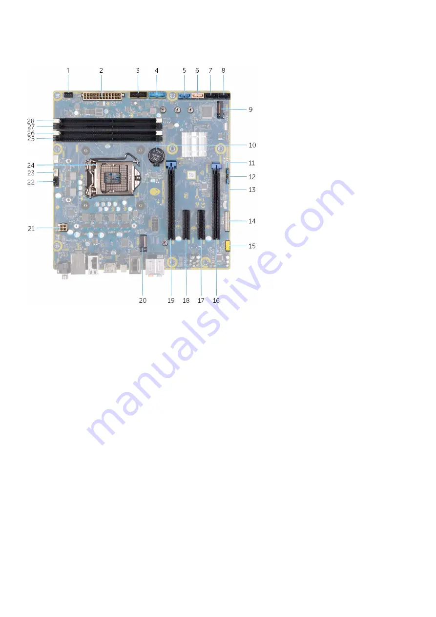
System-board components

1. front-chassis fan connector (FRONT_FAN)

2. power-supply connector

3. front-panel USB cable 2 (F_USB2)

4. front-panel USB cable 1 (F_USB1)

5. SATA 6 Gbps drive connector (SATA1)

6. SATA 6 Gbps drive connector (SATA2)

7. SATA 6 Gbps drive connector (SATA3)

8. SATA 6 Gbps drive connector (SATA4)

9. solid-state drive slot (M.2 SSD)

10. coin-cell battery

11. Service mode (SERVICE MODE)

12. CMOS reset jumper (CMOS_CLR)

13. Password reset jumper (PW_CLR)

14. LED controller connector (LED_CONTROLLER)

15. front audio connector (F_AUDIO)

16. PCI-Express x8 slot (SLOT4)

17. PCI-Express x4 slot (SLOT3)

18. PCI-Express x4 slot (SLOT3)

19. PCI-Express x16 mechanical/x8 electrical slot (SLOT1)

20. wireless-card slot (M.2 WIFI)

21. processor connector (AIX_CPU)

22. top-chassis fan (TOP_FAN)

23. processor-cooling assembly pump-fan connector 

(PUMP_FAN)

24. processor socket (CPU1)

25. memory-module slot 3 (DDR4/XMM3)

26. memory-module slot 1 (DDR4/XMM1)

27. memory-module slot 2 (DDR4/XMM2)

28. memory-module slot 4 (DDR4/XMM4)

Recommended tools

The procedures in this document may require the following tools:

Philips screwdriver #1

Flat-head screwdriver

Plastic scribe

10

Summary of Contents for Aurora R9

Page 1: ...Alienware Aurora R9 Service Manual Regulatory Model D23M Regulatory Type D23M002 ...

Page 2: ...age to hardware or loss of data and tells you how to avoid the problem WARNING A WARNING indicates a potential for property damage personal injury or death 2018 2019 Dell Inc or its subsidiaries All rights reserved Dell EMC and other trademarks are trademarks of Dell Inc or its subsidiaries Other trademarks may be trademarks of their respective owners 2019 08 Rev A00 ...

Page 3: ...oving the right side cover 15 Installing the right side cover 16 2 5 inch hard drive 18 Removing the 2 5 inch hard drive 18 Installing the 2 5 inch hard drive 19 3 5 inch hard drive 21 Removing the 3 5 inch hard drive 21 Installing the 3 5 inch hard drive 22 2 5 inch hard drive cage 24 Removing the 2 5 inch hard drive cage 24 Installing the 2 5 inch hard drive cage 25 3 5 inch hard drive cage 25 R...

Page 4: ...el 57 Removing the front bezel 57 Installing the front bezel 60 Top bezel 65 Removing the top bezel 65 Installing the top bezel 66 Bottom cover 67 Removing the bottom cover 67 Installing the bottom cover 68 Processor fan and heat sink assembly 69 Removing the processor fan and heat sink assembly 69 Installing the processor fan and heat sink assembly 70 Processor 72 Removing the processor 72 Instal...

Page 5: ...93 Downloading the media card reader driver 94 Downloading the chipset driver 94 Downloading the network driver 95 4 System setup 96 System setup 96 Entering BIOS setup program 96 Navigation keys 96 Boot Sequence 96 System setup options 97 Clearing CMOS settings 99 Clearing forgotten password 100 5 Troubleshooting 102 Enhanced Pre Boot System Assessment ePSA diagnostics 102 Running the ePSA diagno...

Page 6: ...u work periodically touch an unpainted metal surface to dissipate static electricity which could harm internal components CAUTION When you disconnect a cable pull on its connector or on its pull tab not on the cable itself Some cables have connectors with locking tabs or thumb screws that you must disengage before disconnecting the cable When disconnecting cables keep them evenly aligned to avoid ...

Page 7: ...atic mat is dissipative and parts can be placed on it during service procedures When using an anti static mat your wrist strap should be snug and the bonding wire should be connected to the mat and to any bare metal on the system being worked on Once deployed properly service parts can be removed from the ESD bag and placed directly on the mat ESD sensitive items are safe in your hand on the ESD m...

Page 8: ...mponents Transporting sensitive components When transporting ESD sensitive components such as replacement parts or parts to be returned to Dell it is critical to place these parts in anti static bags for safe transport Lifting equipment Adhere to the following guidelines when lifting heavy weight equipment CAUTION Do not lift greater than 50 pounds Always obtain additional resources or use a mecha...

Page 9: ...nts Inside view of your computer 1 power supply unit 2 2 5 inch hard drive 3 2 5 inch hard drive cage 4 graphics card 5 system board 6 VR heat sink 7 processor fan and liquid cooling assembly 8 top cover 9 3 5 inch hard drive cage 9 ...

Page 10: ...oller connector LED_CONTROLLER 15 front audio connector F_AUDIO 16 PCI Express x8 slot SLOT4 17 PCI Express x4 slot SLOT3 18 PCI Express x4 slot SLOT3 19 PCI Express x16 mechanical x8 electrical slot SLOT1 20 wireless card slot M 2 WIFI 21 processor connector AIX_CPU 22 top chassis fan TOP_FAN 23 processor cooling assembly pump fan connector PUMP_FAN 24 processor socket CPU1 25 memory module slot ...

Page 11: ... Screw list Component Secured to Screw type Quantity Screw image Side panel release latch Chassis M3x4 1 2 5 inch hard drive cage Chassis 6 32 2 3 5 inch hard drive cage Chassis 6 32 2 Power supply unit bracket Power supply unit cage 6 32 2 Power supply unit Chassis 6 32 4 Right tron light board Chassis 6 32 4 Radiator and fan assembly Radiator and fan cage 6 32 4 Antennas Chassis M3x4t 4 Top beze...

Page 12: ... that secures the side cover release latch to the chassis 2 Pull the side cover release latch to release the left side cover away from the chassis 3 Lift the left side panel from the chassis Installing the left side cover Prerequisites If you are replacing a component remove the existing component before performing the installation procedure About this task The following images indicate the locati...

Page 13: ...side cover release latch to the chassis Next steps 1 Follow the procedure in After working inside your computer Top cover Removing the top cover Prerequisites 1 Follow the procedure in Before working inside your computer 2 Remove the left side cover About this task The following images indicate the location of the top cover and provides a visual representation of the removal procedure 13 ...

Page 14: ...and may requires force to remove it off the chassis Installing the top cover Prerequisites If you are replacing a component remove the existing component before performing the installation procedure About this task The following images indicate the location of the top cover and provides a visual representation of the installation procedure 14 ...

Page 15: ...ure in After working inside your computer Right side cover Removing the right side cover Prerequisites 1 Follow the procedure in Before working inside your computer 2 Remove the left side cover 3 Remove the top cover About this task The following images indicate the location of the right side cover and provides a visual representation of the removal procedure 15 ...

Page 16: ...om the chassis Installing the right side cover Prerequisites If you are replacing a component remove the existing component before performing the installation procedure About this task The following images indicate the location of the right side cover and provides a visual representation of the installation procedure 16 ...

Page 17: ...17 ...

Page 18: ...tall the left side cover 3 Follow the procedure in After working inside your computer 2 5 inch hard drive Removing the 2 5 inch hard drive Prerequisites 1 Follow the procedure in Before working inside your computer 2 Remove the left side cover About this task The following images indicate the location of the 2 5 inch hard drive and provides a visual representation of the removal procedure 18 ...

Page 19: ... the hard drive assembly NOTE Note the orientation of the hard drive so that you can replace it correctly NOTE Repeat the steps to remove any additional 2 5 inch hard drive from your computer Installing the 2 5 inch hard drive Prerequisites If you are replacing a component remove the existing component before performing the installation procedure About this task The following images indicate the l...

Page 20: ...NOTE Note the orientation on the hard drive carrier to replace it correctly 20 ...

Page 21: ...drive NOTE Repeat the steps to install any additional 2 5 inch hard drive from your computer Next steps 1 Install the left side cover 2 Follow the procedure in After working inside your computer 3 5 inch hard drive Removing the 3 5 inch hard drive Prerequisites 1 Follow the procedure in Before working inside your computer 2 Remove the left side cover About this task The following images indicate t...

Page 22: ...he hard drive 4 Lift the hard drive out of the hard drive assembly NOTE Note the orientation of the hard drive so that you can replace it correctly Installing the 3 5 inch hard drive Prerequisites If you are replacing a component remove the existing component before performing the installation procedure About this task The following images indicate the location of the 3 5 inch hard drive and provi...

Page 23: ...NOTE Note the orientation on the hard drive carrier to replace it correctly 23 ...

Page 24: ...er 2 5 inch hard drive cage Removing the 2 5 inch hard drive cage Prerequisites 1 Follow the procedure in Before working inside your computer 2 Remove the left side cover 3 Remove the 2 5 inch hard drive if installed About this task The following images indicate the location of the 2 5 inch and provides a visual representation of the removal procedure Steps 1 Remove the two screws 6 32 that secure...

Page 25: ...ign the tabs on the cage with the tabs on the chassis 3 Replace the two screws 6 32 that secure the 2 5 inch hard drive cage to the chassis NOTE Repeat the procedure from step 1 to step 3 to install the other 2 5 inch hard drive cage Next steps 1 Install the 2 5 inch hard drive if required 2 Install the left side cover 3 Follow the procedure in After working inside your computer 3 5 inch hard driv...

Page 26: ...d drive cage to the chassis 2 Lift the 3 5 inch hard drive cage off the chassis Installing the 3 5 inch hard drive cage Prerequisites If you are replacing a component remove the existing component before performing the installation procedure About this task The following images indicate the location of the 3 5 inch hard drive cage and provides a visual representation of the installation procedure ...

Page 27: ...n After working inside your computer 460 W power supply unit Removing the 460 W power supply unit Prerequisites 1 Follow the procedure in Before working inside your computer 2 Remove the left side cover NOTE Note the routing of all cables as you remove them so that you can route them correctly after you replace the power supply unit About this task The following images indicate the location of the...

Page 28: ...28 ...

Page 29: ...er cables from the graphics card 5 Disconnect the power cables from the hard drives 6 Disconnect the processor power cable and system board power cable from the system board 7 Rotate the power supply unit cage towards the chassis 8 Remove the four screws 6 32 that secure the power supply unit to the chassis 9 Slide and lift the power supply unit along with the cables off the chassis Installing the...

Page 30: ... power wattage Ensure that you plug in the cable to the correct port Failure to do so may result in damaging the power supply unit and or system components About this task The following images indicate the location of the power supply unit and provides a visual representation of the installation procedure 30 ...

Page 31: ...to the graphics card 8 Rotate the power supply unit cage towards the chassis 9 Slide the power supply unit cage release latches towards the locked position 10 Align the screw holes on the power supply unit bracket with the screw holes on the power supply unit cage 11 Replace the two screws 6 32 that secure the power supply unit bracket to the power supply unit cage Next steps 1 Install the left si...

Page 32: ...t bracket to the power supply unit cage 2 Lift the power supply unit bracket off the power supply unit cage 3 Press the releasing clip on the power cable connectors and disconnect all the power cables from the power supply unit 4 Remove the four screws 6 32 that secure the power supply unit to the chassis 5 Slide and lift the power supply unit along with the cables off the chassis Installing the 8...

Page 33: ...lation procedure Steps 1 Place the power supply on the chassis 2 Align the screw holes on the power supply unit with the screw holes on the chassis 3 Replace the four screws 6 32 that secure the power supply unit to the chassis 4 Connect all the power cables to the power supply unit 5 Align the screw holes on the power supply unit bracket with the screw holes on the power supply unit cage 6 Replac...

Page 34: ... the top cover 4 Remove the right side cover About this task The following images indicate the location of the right tron light board and provides a visual representation of the removal procedure Steps 1 Disconnect the tron light cable 2 Remove the four screws 6 32 that secure the right tron light board to the chassis 3 Remove the right tron light board off the chassis 34 ...

Page 35: ...board and provides a visual representation of the installation procedure Steps 1 Align the screw holes on the right tron light board with the screw holes on the chassis 2 Replace the four screws 6 32 that secure the right tron light board to the chassis 3 Connect the tron light cable Next steps 1 Install the right side cover 2 Install the top cover 3 Install the left side cover 4 Follow the proced...

Page 36: ... cool before you touch it CAUTION To ensure maximum cooling for the processor do not touch the heat transfer areas on the processor liquid cooling assembly The oils in your skin can reduce the heat transfer capability of the thermal grease 2 Remove the left side cover 3 Remove the top cover 4 Remove the right side cover 5 Remove the memory modules About this task The following images indicate the ...

Page 37: ... the radiator and fan assembly to the radiator and fan cage 7 Lift the VR heat sink off the computer 8 Disconnect the processor cooling assembly cables from the system board 9 In the reverse sequential order as indicated on the processor cooler loosen the four captive screws that secure the processor cooler to the system board NOTE If your are using an electric screwdriver torque the screws at 6 9...

Page 38: ... before performing the installation procedure CAUTION Incorrect alignment of the processor liquid cooling assembly can damage the system board and processor About this task The following images indicate the location of the processor liquid cooling assembly and provides a visual representation of the installation procedure 38 ...

Page 39: ...r captive screws that secure the processor cooler to the system board NOTE If your are using an electric screwdriver torque the screws at 6 9 1 15 kilogram force centimeter 6 1 pound force inch 6 Connect the processor cooling assembly cables to the system board 7 Replace the four screws 6 32 that secure the radiator and fan assembly to the chassis 8 Rotate the power supply unit cage towards the ch...

Page 40: ... instructions in After working inside your computer For more safety best practices see the Regulatory Compliance home page at www dell com regulatory_compliance CAUTION Removing the coin cell battery resets the BIOS setup program s settings to default It is recommended that you note the BIOS setup program s settings before removing the coin cell battery 2 Remove the left side cover About this task...

Page 41: ...lease lever away from the coin cell battery until the coin cell battery pops up 5 Lift the coin cell battery out of its socket Installing the coin cell battery Prerequisites If you are replacing a component remove the existing component before performing the installation procedure About this task The following images indicate the location of the coin cell battery and provides a visual representati...

Page 42: ...Steps 1 Insert a new coin cell battery CR2032 into the battery socket with the positive side facing up and snap the battery into place 42 ...

Page 43: ... side cover 2 Follow the procedure in After working inside your computer Memory modules Removing the memory modules Prerequisites 1 Follow the procedure in Before working inside your computer 2 Remove the left side cover About this task The following images indicate the location of the memory modules and provides a visual representation of the removal procedure 43 ...

Page 44: ...out of the memory module slot NOTE Repeat step 5 to step 6 to remove any other memory modules installed in your computer CAUTION To prevent damage to the memory module hold the memory module by the edges Do not touch the components on the memory module Installing the memory modules Prerequisites If you are replacing a component remove the existing component before performing the installation proce...

Page 45: ...Steps 1 Ensure that the securing clips are extended away from the memory module slot 45 ...

Page 46: ... available memory configuration matrix Table 2 Memory configuration matrix Configuration Slot XMM1 XMM2 XMM3 XMM4 8 GB DDR4 8 GB 16 GB DDR4 8 GB 8 GB 32 GB DDR4 16 GB 16 GB 64 GB DDR4 16 GB 16 GB 16 GB 16 GB 16 GB XMP 8 GB 8 GB 32 GB XMP 16 GB 16 GB 64 GB XMP 16 GB 16 GB 16 GB 16 GB Next steps 1 Remove the left side cover 2 Follow the procedure in After working inside your computer Solid state dri...

Page 47: ...te drive Prerequisites If you are replacing a component remove the existing component before performing the installation procedure CAUTION Solid state drives are fragile Exercise care when handling the solid state drive About this task The following images indicate the location of the solid state drive and provides a visual representation of the installation procedure 47 ...

Page 48: ...system board Next steps 1 Install the single graphics card or dual graphics card as applicable 2 Install the left side cover 3 Follow the procedure in After working inside your computer Single graphics card Removing the single graphics card Prerequisites 1 Follow the procedure in Before working inside your computer 2 Remove the left side cover About this task The following images indicate the loca...

Page 49: ...49 ...

Page 50: ...r cable connectors and disconnect the power cables from the graphics card 6 Push the securing tab on the PCIe slot away from the graphics card grasp the card by its top corner and ease it out of the slot Installing the single graphics card Prerequisites If you are replacing a component remove the existing component before performing the installation procedure About this task The following images i...

Page 51: ...51 ...

Page 52: ...s the chassis 5 Slide the power supply unit cage release latches towards the locked position Next steps 1 Install the left side cover 2 Follow the procedure in After working inside your computer Dual graphics card Removing the dual graphics card Prerequisites 1 Follow the procedure in Before working inside your computer 2 Remove the left side cover About this task The following images indicate the...

Page 53: ...53 ...

Page 54: ...release the graphics card bracket from the chassis 6 Press the releasing clip on the power cable connectors and disconnect the power cables from the graphics card 7 Push the securing tab on the PCIe slot away from the graphics card grasp the card by its top corner and ease it out of the slot on the PCI Express x8 slot 8 Push the securing tab on the PCIe slot away from the graphics card grasp the c...

Page 55: ...ou are replacing a component remove the existing component before performing the installation procedure About this task The following images indicate the location of the graphics card and provides a visual representation of the installation procedure 55 ...

Page 56: ...56 ...

Page 57: ...aphics card bracket into the slot on the chassis and snap it into place 6 Replace the graphics bridge that connects the graphics cards 7 Rotate the power supply unit cage towards the chassis 8 Slide the power supply unit cage release latches towards the locked position Next steps 1 Install the left side cover 2 Follow the procedure in After working inside your computer Front bezel Removing the fro...

Page 58: ...ide cover 5 Remove the single graphics card or dual graphics card as applicable About this task The following images indicate the location of the front bezel and provides a visual representation of the removal procedure 58 ...

Page 59: ...59 ...

Page 60: ...audio cable from the system board and remove the cables from the routing guides on the inside of the chassis 8 Place the computer in an upright position 9 Disconnect the tron light cable and then remove the cable from the routing guides on the chassis 10 Grasp and release the front bezel tabs sequentially from the top by moving them outward from the front panel 11 Remove the power button module ca...

Page 61: ...About this task The following images indicate the location of the front bezel and provides a visual representation of the installation procedure 61 ...

Page 62: ...62 ...

Page 63: ...63 ...

Page 64: ...s 5 Route the power button module cable through the routing guides on the chassis and connect the power button module cable 6 Place the computer in an upright position 7 Route the tron light cable through the routing guides on the chassis and connect the tron light cable 8 Rotate the power supply unit cage towards the chassis 9 Slide the power supply unit cage release latches towards the locked po...

Page 65: ...r 4 Remove the right side cover 5 Remove the wireless card 6 Remove the front bezel About this task The following images indicate the location of the top bezel and provides a visual representation of the removal procedure Steps 1 Remove the four screws 6 32 that secure the top bezel to the right and left of the chassis 2 Lift the top cover off the chassis 65 ...

Page 66: ...sentation of the installation procedure Steps 1 Align the tabs on the top cover with the slots on the chassis and snap the top cover into place 2 Replace the four screws 6 32 that secure the top bezel to the right and left of the chassis Next steps 1 Install the front bezel 2 Install the wireless card 3 Install the right side cover 4 Install the top cover 5 Install the left side cover 6 Follow the...

Page 67: ...he 2 5 inch hard drive cages 6 Remove the front bezel About this task The following images indicate the location of the bottom cover and provides a visual representation of the removal procedure Steps 1 Place the computer on a clean and flat surface with the left side facing up 2 Press the securing tabs to release the bottom cover from the slots on the chassis 3 Remove the bottom cover from the ch...

Page 68: ... provides a visual representation of the installation procedure Steps 1 Align the tabs on the bottom cover with the slots on the chassis 2 Rotate the bottom cover towards the chassis until it snaps into place Next steps 1 Install the front bezel 2 Install the 2 5 inch hard drive cages 3 Install the right side cover 4 Install the top cover 5 Install the left side cover 6 Follow the procedure in Aft...

Page 69: ...ient time for the heat sink to cool before you touch it CAUTION For maximum cooling of the processor do not touch the heat transfer areas on the heat sink The oils in your skin can reduce the heat transfer capability of the thermal grease 2 Remove the left side cover About this task The following images indicate the location of the processor fan and heat sink assembly and provides a visual represe...

Page 70: ...o the system board 6 Lift the processor fan and heat sink assembly off the system board Installing the processor fan and heat sink assembly Prerequisites If you are replacing a component remove the existing component before performing the installation procedure CAUTION If either the processor or the heat sink is replaced use the thermal grease provided in the kit to ensure that thermal conductivit...

Page 71: ...Steps 1 Place the processor fan and heat sink assembly on the processor 71 ...

Page 72: ...working inside your computer 2 Remove the left side cover 3 Remove the processor liquid cooling assembly or processor fan and heat sink assembly as applicable About this task The following images indicate the location of the processor and provides a visual representation of the removal procedure Steps 1 Press the release lever down and then push it away from the processor to release it from the ta...

Page 73: ...ated in the socket close the processor cover 4 Pivot the release lever down and place it under the tab on the processor cover Next steps 1 Install the processor liquid cooling assembly or processor fan and heat sink assembly as applicable 2 Install the left side cover 3 Follow the procedure in After working inside your computer Wireless card Removing the wireless card Prerequisites 1 Follow the pr...

Page 74: ...ess card from the wireless card slot Installing the wireless card Prerequisites If you are replacing a component remove the existing component before performing the installation procedure CAUTION To avoid damage to the wireless mini card do not place any cables under it About this task The following images indicate the location of the wireless card and provides a visual representation of the insta...

Page 75: ...uxiliary black triangle Black 2 Place the wireless card bracket on the wireless card 3 Align the notch on the wireless card with the tab on the wireless card slot 4 Slide the wireless card at an angle into the wireless card slot 5 Replace the screw M2x4 that secures the wireless card to the system board Next steps 1 Install the single graphics card or dual graphics card as applicable 2 Install the...

Page 76: ...ables from the securing clips and routing guides inside the chassis 2 Push down the antenna cables towards the top of the computer through the cable routing slot on the chassis 3 Remove the four screws M3x4t that secures the antennas to the chassis 4 Remove the antenna cables from the routing guides on the top cover 5 Pry the antenna off the chassis Installing the antennas Prerequisites If you are...

Page 77: ...ll the front bezel 2 Install the wireless card 3 Install the right side cover 4 Install the top cover 5 Install the left side cover 6 Follow the procedure in After working inside your computer Front I O panel Removing the front I O panel Prerequisites 1 Follow the procedure in Before working inside your computer 2 Remove the top cover 3 Remove the left side cover 4 Remove the right side cover 5 Re...

Page 78: ...the front bezel Installing the front I O panel Prerequisites If you are replacing a component remove the existing component before performing the installation procedure About this task The following images indicate the location of the front I O panel and provides a visual representation of the installation procedure 78 ...

Page 79: ...de cover 4 Install the top cover 5 Follow the procedure in After working inside your computer Front chassis fan Removing the front chassis fan Prerequisites 1 Follow the procedure in Before working inside your computer 2 Remove the left side cover 3 Remove the single graphics card or dual graphics card as applicable About this task The following images indicate the location of the front chassis fa...

Page 80: ...ft the front chassis fan off the chassis Installing the front chassis fan Prerequisites If you are replacing a component remove the existing component before performing the installation procedure About this task The following images indicate the location of the front chassis fan and provides a visual representation of the installation procedure 80 ...

Page 81: ...ard or dual graphics card as applicable 2 Install the left side cover 3 Follow the procedure in After working inside your computer Top chassis fan Removing the top chassis fan Prerequisites 1 Follow the procedure in Before working inside your computer 2 Remove the left side cover About this task The following images indicate the location of the top chassis fan and provides a visual representation ...

Page 82: ...Steps 1 Lay the computer on the right side 82 ...

Page 83: ... top chassis fan cable from the routing guide on the top chassis fan bracket 8 Push the rubber grommets through the holes at each corner of the fan to release top chassis fan from the bracket 9 Slide the top chassis fan off the top chassis fan bracket Installing the top chassis fan Prerequisites If you are replacing a component remove the existing component before performing the installation proce...

Page 84: ...n to the chassis 5 Route the top chassis fan cable through the routing guide on the bracket 6 Align the tabs on the top chassis fan with the slots on the chassis and slide the fan until it snaps into position 7 Replace the screw that secures the top chassis fan to the chassis 8 Connect the top chassis fan cable to the system board 9 Rotate the power supply unit cage towards the chassis 10 Slide th...

Page 85: ...epresentation of the removal procedure Steps 1 Remove the two screws M2x4 that secure the power button module to the front bezel 2 Lift the power button module off the front bezel 3 Disconnect the cables from the power button module Installing the power button board Prerequisites If you are replacing a component remove the existing component before performing the installation procedure About this ...

Page 86: ...ored in the system board You must enter the Service Tag in the BIOS setup program after you replace the system board NOTE Replacing the system board removes any changes you have made to the BIOS using the BIOS setup program You must make the appropriate changes again after you replace the system board NOTE Before disconnecting the cables from the system board note the location of the connectors so...

Page 87: ...8 Remove the processor About this task The following images indicate the location of the system board and provides a visual representation of the removal procedure 87 ...

Page 88: ...stem board 8 Disconnect the system board power cable from the system board 9 Disconnect the front chassis fan cable from the system board 10 Remove the antenna cables from the routing guides on the chassis 11 Remove the eight screws 6 32 that secure the system board assembly to the chassis 12 Lift the system board off the chassis Installing the system board Prerequisites If you are replacing a com...

Page 89: ...89 ...

Page 90: ...o the system board 11 Route and connect the front panel audio cable to the system board 12 Route and connect the hard drive data cable to the system board 13 Route and connect the front panel USB cables to the system board Next steps 1 Install the processor 2 Install the single graphics card or dual graphics card as applicable 3 Install the processor liquid cooling assembly or processor fan and he...

Page 91: ...t your computer 2 Press F2 when the Dell logo is displayed to enter the BIOS setup program 3 Navigate to the Main tab and enter the Service Tag in the Service Tag Input field Next steps NOTE Service tag is the alphanumeric identifier located at the back side of your computer 91 ...

Page 92: ... all files can be installed automatically Review the installation summary to identify if manual installation is necessary 13 For manual download and installation click Category 14 Click Audio in the drop down list 15 Click Download to download the audio driver for your computer 16 After the download is complete navigate to the folder where you saved the audio driver file 17 Double click the audio ...

Page 93: ...ist NOTE Review on screen instructions for browser specific instructions 8 Click View Drivers for My System 9 Click Download and Install to download and install all driver updates detected for your computer 10 Select a location to save the files 11 If prompted approve requests from User Account Control to make changes on the system 12 The application installs all drivers and updates identified NOT...

Page 94: ...ect Drivers button 6 Review and agree to the Terms and Conditions to use SupportAssist then click Continue 7 If necessary your computer starts to download and install SupportAssist NOTE Review on screen instructions for browser specific instructions 8 Click View Drivers for My System 9 Click Download and Install to download and install all driver updates detected for your computer 10 Select a loca...

Page 95: ...urn on your computer 2 Go to www dell com support 3 Enter the Service Tag of your computer and then click Submit NOTE If you do not have the Service Tag use the auto detect feature or manually browse for your computer model 4 Click Drivers downloads 5 Click the Detect Drivers button 6 Review and agree to the Terms and Conditions to use SupportAssist then click Continue 7 If necessary your computer...

Page 96: ...ges that you make are recorded but do not take effect until you restart the system Keys Navigation Up arrow Moves to the previous field Down arrow Moves to the next field Enter Selects a value in the selected field if applicable or follow the link in the field Spacebar Expands or collapses a drop down list if applicable Tab Moves to the next focus area Esc Moves to the previous page until you view...

Page 97: ...splays the processor type CPU Speed Displays the speed of the processor CPU ID Displays the processor identification code Cache L1 Displays the processor L1 cache size Cache L2 Displays the processor L2 cache size Cache L3 Displays the processor L3 cache size Table 5 System setup options Advanced menu Advanced Advanced BIOS Features Intel SpeedStep Allows you to enable or disable Intel Speedstep T...

Page 98: ...ows you to set the date on which the computer must turn on automatically This option can be configured only if the Auto Power On mode is set to Enabled 1 to 31 Auto Power On Time Allows you to set the time at which the computer must turn on automatically This option can be configured only if the Auto Power On mode is set to Enabled hh mm ss Performance Options Overclocking Feature Core Over Clocki...

Page 99: ...evices Boot Option 1 Displays the first boot device Default UEFI Windows Boot Manager Boot Option 2 Displays the second boot device Default Onboard NIC Device Boot Option 3 Displays the third boot device Default Onboard NIC Device Table 8 System setup options Exit menu Save Exit Save Changes and Reset Allows you to exit system setup and save your changes Discard Changes and Reset Allows you to exi...

Page 100: ...nnect the system board power cable to the system board Next steps 1 Remove the left side cover 2 Follow the procedure in After working inside your computer Clearing forgotten password Prerequisites 1 Follow the procedure in Before working inside your computer 2 Remove the left side cover About this task The following images indicate the location of the memory modules and provide a visual represent...

Page 101: ... Turn on your computer and wait until the operating system is completely loaded 3 Shut down your computer 4 Replace the jumper plug on pins 215 Next steps 1 Remove the left side cover 2 Follow the procedure in After working inside your computer 101 ...

Page 102: ... Dell logo appears 3 On the boot menu screen select the Diagnostics option 4 Click the arrow at the bottom left corner Diagnostics front page is displayed 5 Click the arrow in the lower right corner to go to the page listing The items detected are listed 6 To run a diagnostic test on a specific device press Esc and click Yes to stop the diagnostic test 7 Select the device from the left pane and cl...

Page 103: ...ate a bootable USB drive For more information see the knowledge base article SLN143196 at www dell com support 3 Copy the BIOS setup program file to the bootable USB drive 4 Connect the bootable USB drive to the computer that needs the BIOS update 5 Restart the computer and press F12 when the Dell logo is displayed on the screen 6 Boot to the USB drive from the One Time Boot Menu 7 Type the BIOS s...

Page 104: ...less router 4 Wait for 30 seconds 5 Turn on the wireless router 6 Turn on the modem 7 Turn on your computer Flea power release About this task Flea power is the residual static electricity that remains on the computer even after it has been powered off and the battery has been removed The following procedure provides the instructions on how to conduct flea power release Steps 1 Turn off your compu...

Reviews: