www.alfatronelectronics.com
ALFATRON ELECTRONICS GmbH GERMANY
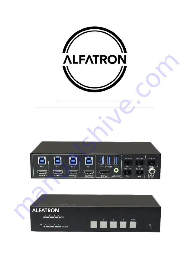
ALF-WU4K HUB
4K HDMI 2.0 4x1 Switcher with KVM USB3.0
All Rights Reserved
Page 1: ...www alfatronelectronics com ALFATRON ELECTRONICS GmbH GERMANY ALF WU4K HUB 4K HDMI 2 0 4x1 Switcher with KVM USB3 0 All Rights Reserved...
Page 2: ...tatement This equipment generates uses and can radiate radio frequency energy and if not installed and used in accordance with the instructions may cause harmful interference to radio communications I...
Page 3: ...or install this product near water Do not put any heavy items on the extension cable in case of extrusion Do not remove the housing of the device as opening or removing housing may expose you to dang...
Page 4: ...stem Diagram 5 5 Button Control 6 6 Table Grommet Control 6 7 RS232 Control 7 7 1 RS232 Control Software 7 7 2 RS232 Command 9 7 2 1 Device Control 9 7 2 2 Signal Switching 10 7 2 3 Audio Setting 11 7...
Page 5: ...e controlled via RS232 and front panel buttons 1 1 Features 4x1 HDMI 2 0 Switcher with KVM Supports video resolution up to 4Kx2K 60Hz 4 4 4 HDR 10 and Dolby Vision HDCP 2 2 compliant Compatible with W...
Page 6: ...or 1 3 5mm mini stereo audio jack Audio Format PCM 2CH Frequency Response 20Hz to 20KHz 1dB Max Output Level 2 0Vrms 0 5dB 2V 16dB headroom above 10dBV 316 mV nominal consumer line level signal THD N...
Page 7: ...ion 3 1 Front Panel POWER LED The LED illuminates red when power is applied PC LEDs Total four LEDs any one of which illuminates blue to indicate its corresponding type B USB port is connected to an a...
Page 8: ...o control the PC which is connected to the selected HDMI input port and the corresponding type B USB port These type A USB ports can power these USB devices with 1A DISPLAY Type A female HDMI output p...
Page 9: ...er cords should be insulated and safe All devices should be connected before power on 4 2 System Diagram The following diagrams illustrate typical input and output connections that can be utilized wit...
Page 10: ...input signal source 5V Default or TMDS Reboot Once power is restored to the switcher if the last selected source is still available the switcher will still output this signal otherwise the switcher wi...
Page 11: ...ontrol Software Installation Copy the control software file to the computer connected with this switcher Uninstallation Delete all the control software files in corresponding file path Basic Settings...
Page 12: ...arameters of COM number bound rate data bit stop bit and the parity bit correctly then the RS232 commands can be sent in Command Sending Area Baud rate 9600 Data bit 8 Stop bit 1 Parity bit none Param...
Page 13: ...AUTO button AUTO PANEL UNLOCK SET_AUTO_KEY_LOCK 1 Lock the AUTO button AUTO PANEL LOCK GET_AUTO_KEY_LOCK Get the locking status of AUTO button AUTO PANEL UNLOCK AUTO PANEL LOCK SET_HDMI_DETECTION _MO...
Page 14: ...ATE IS 1 REBOOT Reboot the device REBOOT HELP Get all commands and its usage 7 2 2 Signal Switching Command Description Command Example and Feedback SET_AV H1 Switch to HDMI source 1 HDMI IN SWITCH TO...
Page 15: ...4 SET_SWITCH_USB 1 SET SWITCH MODE 1 SET USB SWITCH TO 1 GET_SWITCH_USB Get the PC which switching USB to USB SWITCH TO 1 SET_USB_SWITCH_MO DE 0 Set USB switching mode to follows the video switching S...
Page 16: ...ode EDID_MODE 0000 EDIDR PARAM Get the EDID value PARAM 0000 0011 EDID HEX STRING OF 0000 00 FF FF FF FF FF FF 00 41 0C F2 08 50 12 00 00 UPLOAD_USER_EDID PARAM PARAM 0001 0010 0011 upload user define...
Page 17: ...BAUDRATE IS 1 SET_RS232_BAUD 2 Set RS232 baud rate to 19200 RS232 BAUDRATE IS 2 SET_RS232_BAUD 3 Set RS232 baud rate to 38400 RS232 BAUDRATE IS 3 SET_RS232_BAUD 4 Set RS232 baud rate to 57600 RS232 B...
Page 18: ...d of BOOTDISK 4 Double click the U disk a file named of READY TXT would be showed 5 Directly copy the latest upgrade file bin to the BOOTDISK U disk 6 Reopen the U disk to check the filename READY TXT...
Page 19: ...oose connection Make sure the connection is good The switcher is broken Send it to an authorize dealer for repairing POWER indicator doesn t work or no respond to any operation Fail connection of powe...
Page 20: ...ure of the product due to insufficient or improper maintenance is not covered 1 4 The Company does not warrant that the product covered hereby including without limitation the technology and or integr...
Page 21: ...sts related to any setting up this product any adjustment of user controls or any programming required for a specific installation of this product 1 13 Please be aware that the Company s products and...