ALFAtron ALF-12X-NDIC User Manual Download Page 32

ALFATRON ALF-12X-NDIC, ALF-20X-NDIC and ALF-30X-NDIC


26 

Select users: Set the user type (the default administrator, Common User 1, Common User 2 optional) 

Username: set the username (Select User Administrator default admin; select a common user1 default user1; to select a 

common user 2 default user2; user can modify their own) 

Password: Set a password (Select User Administrator default admin; select a common user1 default user1; to select a 

common user 2 default user2; user can modify their own). 

Password confirmation: Confirm the input passwords are the same or not. 

Click on the "Save" button to display the "Save successfully" message, then the set is to take effect. 

Note: Please note the case-sensitivity of the username and password. 

If login page by a common user’s name and password, one does not have configuration privileges but can only operate to 

preview, playback, logoff. 


4) Version upgrade 

MCU version V2.0.0.16 2015-12-18 

Camera version V2.0.0.16 2015-12-18 

Focus version V2.0.0.6 2015-12-11 

Users only read the version information above which is consistent with the menu version but cannot modify. Different types 

of the machine have different information. 

Update file: 

Click "Browse ..." installation, to select the upgrade file in the pop-up window. 

Click on the "Upgrade" button, the upgrade dialog will appear. the device will reboot automatically after update successfully. 

(Note: make sure the power and network are keeping connected during the process. Or the upgrade will fail) 


Note: After the version upgrade is complete, you need to restore factory defaults; a, through web to restore the factory 

default configuration; b, through the recovery menu; c, remote control shortcut * # 6;   

Choose one of the above three ways. If chose a, the IP accounts, passwords also need to be restored to the default. 


5) Restore factory setting


Click on pop-up "Restore Factory Defaults" button and choose “yes” or “no”, then the device will restart automatically and 

restore factory setting. 


6) Reboot 

Click on the pop-up "Reboot" button and choose “yes” or “no”, then the device will restart automatically


4.2.8 Logout 

Point "Logout" pop-up "Confirmation" dialog; select "Yes" or "No”, choose “Yes” to exit the current page and return to the 

user login interface again. 


5. Serial Communication Control 

 
Under common working  condition, the  camera could  be controlled through RS232/RS485 interface 
(VISCA), RS232C serial parameter are as follows: 

Baud rate: 2400/4800/9600/115200 bits / sec; Start bit: 1; data bits: 8; Stop bit: 1; Parity: None. 

After power on, the camera first goes left, then back to the middle position. Self-test is finished after the zoom moved to the 

farthest and then back to the nearest position. If the camera saved 0 preset before, it will be back to that position after 

initialization. At this point, the user can control the camera by the serial commands.         


5.1 VISCA protocol list 

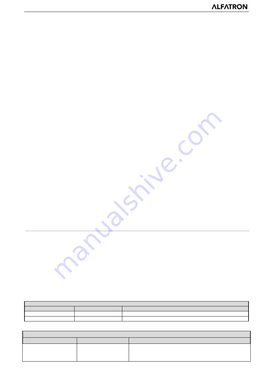
5.1.1 Camera return command 

Ack/Completion Message 


Command packet 

Note   

ACK 

z0 41 FF 

Returned when the command is accepted.   

Completion 

z0 51 FF 

Returned when the command has been executed. 

z = camera a 8 


Error Messages 


Command packet 

Note   

Syntax Error 

z0 60 02 FF 

Returned when the command format is different or when a 

command with illegal command parameters is accepted 

Summary of Contents for ALF-12X-NDIC

Page 1: ...1 www alfatronelectronics com ALFATRON ELECTRONICS GmbH GERMANY ALF 12X NDIC ALF 20X NDIC ALF 30X NDIC Full HD PTZ Camera User Manual...

Page 2: ...er or an experienced radio TV technician for help WARNING Changes or modifications not expressly approved by the party responsible for compliance could void the user s authority to operate the equipme...

Page 3: ...ong or corrosive detergents to avoid scratching the lens and affecting the image This product has no parts that users can repair by themselves and the damage caused by users self disassembly does not...

Page 4: ...not be tilted otherwise the picture may be skewed Installation ensures that there are no obstacles in the rotating range of the platform to prevent damage to the rotating shaft of the structure Do not...

Page 5: ......

Page 6: ...4 3 RS 232 Interface 9 3 Application Instruction 10 3 1 Video Output 11 3 1 1 Power On Initial Configuration 11 3 1 2 Video Output 11 3 2 Remote Controller 11 3 2 1 Keys Instruction 11 3 2 2 Applicati...

Page 7: ...26 5 1 1 Camera return command 26 5 1 2 Camera control command 27 5 1 3 Inquiry command 29 5 2 Pelco D protocol command list 31 5 3 Pelco P protocol command list 31 6 Camera Maintenance and Troublesho...

Page 8: ...receiver light stops blinking the self checking is finished Note If you set preset 0 when Power on self test is completed the camera automatically moves to the preset 0 position 1 3 Video Output Vide...

Page 9: ...ATRON ALF 12X NDIC ALF 20X NDIC and ALF 30X NDIC 3 1 4 Bracket mount Note Bracket can only be wall mounted or ceiling mounted on a concrete wall and cannot be installed on plasterboard 1 Wall mount st...

Page 10: ...ALFATRON ALF 12X NDIC ALF 20X NDIC and ALF 30X NDIC 4 2 Ceiling mount steps...

Page 11: ...roduct Introduction 2 1 2 Dimension Camera dimension 2 1 3 Accessory When you unpack check that all the supplied accessories are included Standard 1x Power adapter 1x RS232 cable User manual 4x Double...

Page 12: ...uts support HDMI 3G SDI USB wired LAN and wireless LAN interfaces The 3G SDI is available for 100m transmission at 1080p60 format 7 Multiple Remote Controls There is IR remoter and 2 4G wireless remot...

Page 13: ...c Shutter Auto Manual BLC ON OFF WDR OFF Dynamic level adjustment Video Adjustment Brightness Color Saturation Contrast Sharpness B W mode Gamma curve SNR 55dB Input Output Interface Video Interfaces...

Page 14: ...95 Working temperature 10 50 Working humidity 20 80 Dimension 150mmX150mmX167 5mm Weight 1 4KG Remote Operation IP Remote Upgrade Reboot and Reset Accessories Accessories with camera 12V 1 5A power su...

Page 15: ...ble 2 2 Dial Switch setting 2 4 3 RS 232 Interface 1 RS 232C interface specification as shown below Computer or keyboard and camera connection method Camera WindowsDB 9 1 DTR 1 DCD 2 DSR 2 RXD 3 TXD 3...

Page 16: ...nd output interface so you can cascade as shown above 3 Application Instruction NO Port Definition 1 DTR Data Terminal Ready 2 DSR Data Set Ready 3 TXD Transmit Data 4 GND System Ground 5 RXD Receive...

Page 17: ...nterface then the monitor output image 3 2 Remote Controller 3 2 1 Keys Instruction 1 Standby Key After 3S long press the camera will step into standby mode Long press 3S again the camera will self te...

Page 18: ...te controller button the indicator light is flashing release the button the indicator light stops flashing Users can control the pan tilt zoom setting and running preset positions via the IR remote co...

Page 19: ...reset Note 10 preset positions in total are available by remote controller 2 Preset Running Press a number key 0 9 directly to run a relative preset Note Action in vain if a relative preset position i...

Page 20: ...inter to the Setup in the Main Menu click the HOME key and enter into the System Setting as shown below PROTOCOL VISCA Pleco P Pleco D Auto Visca ADDR VISCA 1 7 Pelco P 1 255 Pelco D 1 255 Baud rate 2...

Page 21: ...ON BLC ON OFF for options only available in auto mode Anti Flicker OFF 50Hz 60Hz for options only available in Auto Iris priority Brightness priority modes Gain Limit 0 15 only available in Auto Iris...

Page 22: ...100 110 120 130 Hue 0 14 AWB Sensitivity high middle low Color Style Default style1 4 Color Temp high middle low 3 IMAGE Move the pointer to the IMAGE in the Menu click the HOME and enter the IMAGE as...

Page 23: ...e 1 7 3D Noise Reduction Close 1 8 Dynamic Hot Pixel Close 1 5 3 3 4 P T Z Move the pointer to the P T Z in the Main Menu click the HOME and enter the P T Z as follow Depth of Field Only effective for...

Page 24: ...sion Move the pointer to the VERSION in the Main Menu click the HOME and enter the VERSION as follow MCU Version Display MCU version information Camera Version Display camera version information AF Ve...

Page 25: ...ty lowered by unstable signal transmission due to poor contact of cables The computer must have the network segment where the camera IP address belongs to The device will not be accessible if without...

Page 26: ...dress to be added cannot be same with that of other computers or devices The existence of this IP address needs to be verified before adding Click the Start and select Operation to input cmd as pictur...

Page 27: ...login as administrator and normal user If login as administrator Default User name Password admin users can preview playback configuration and cancel in the Web Client If login in as normal user Defau...

Page 28: ...file Image File and click Search and search out the video file click Play to play the image file 4 2 4 Configuration Click Configuration to enter the device parameters setting page There are the follo...

Page 29: ...tream 1 300F optional secondary stream 1 150F optional Stream Name When streaming via rtsp or rtmp user can modify stream name Mainstream live av0 sub stream live av1 Click the Save button to display...

Page 30: ...l correction available 2D Noise Reduction Set 2D noise reduction level default Auto 1 7 and Off optional 3D Noise Reduction Set 3D noise reduction level default 5 1 8 and Off optional Dynamic dead pix...

Page 31: ...1 Register Username IPC Register Password 12345678 Equipment ownership Users can add their own Administrative regions Users can add their own Alarm Zone Users can add their own Equipment installation...

Page 32: ...is complete you need to restore factory defaults a through web to restore the factory default configuration b through the recovery menu c remote control shortcut 6 Choose one of the above three ways...

Page 33: ...Variable 8x 01 04 08 2p FF p 0 low F high Near Variable 8x 01 04 08 3p FF Direct 8x 01 04 48 0p 0q 0r 0s FF pqrs Focus Position Auto Focus 8x 01 04 38 02 FF One Push Mode 8x 01 04 38 04 FF Manual Foc...

Page 34: ...E 00 00 0p 0q FF pq ExpComp Position CAM_Back Light On 8x 01 04 33 02 FF Back Light Compensation Off 8x 01 04 33 03 FF CAM_WDRStrength Reset 8x 01 04 21 00 FF WDR Level Setting Up 8x 01 04 21 02 FF Do...

Page 35: ...speed 0x01 low speed to 0x18 high speed WW Tilt speed 0x01 low speed to 0x14 high speed YYYY Pan Position ZZZZ Tilt Position Down 8x 01 06 01 VV WW 03 02 FF Left 8x 01 06 01 VV WW 01 03 FF Right 8x 0...

Page 36: ...0Hz 2 60Hz CAM_ApertureInq 8x 09 04 42 FF y0 50 00 00 0p 0q FF pq Aperture Gain CAM_PictureEffectModeInq 8x 09 04 63 FF y0 50 00 FF Off y0 50 04 FF B W CAM_MemoryInq 8x 09 04 3F FF y0 50 0p FF p Memor...

Page 37: ...Pan Speed Tilt Speed SUM DownLeft 0xFF Address 0x00 0x14 Pan Speed Tilt Speed SUM DownRight 0xFF Address 0x00 0x12 Pan Speed Tilt Speed SUM Zoom In 0xFF Address 0x00 0x20 0x00 0x00 SUM Zoom Out 0xFF A...

Page 38: ...ion Response 0xA0 Address 0x00 0x59 Value High Byte Value Low Byte 0xAF XOR Query Tilt Position 0xA0 Address 0x00 0x53 0x00 0x00 0xAF XOR Query Tilt Position Response 0xA0 Address 0x00 0x5B Value High...

Page 39: ...be displayed menu will automatically exist 30s later then it can be controlled by remote controller 5 Serial port cannot work a Check whether the camera serial device protocol baud rate address is con...

Page 40: ...cturer s product specific warranties against any defect attributable to faulty workmanship or materials fair wear and tear being excluded 1 7 This limited warranty only covers the cost of faulty goods...

Page 41: ...ity or condition of the goods or their failure to correspond with specification shall be notified in writing to the Company within 7 days of delivery or where the defect or failure was not apparent on...

Reviews: