Alfa Laval FrontLine WideGap 100 Instruction Manual Download Page 8

Description

Name plate

The type of unit, manufacturing number and manufacturing year can be found on the name
plate. Pressure vessel details in accordance with the applicable pressure vessel code are also
given. The name plate is fixed to the frame plate, most commonly, or the pressure plate. The
name plate can be a steel plate or a sticker label.

Warning!

The design pressures and temperatures for each unit are marked on the name plate.
These must not be exceeded.

Caution!

Avoid aggressive chemicals for cleaning the heat exchanger when a sticker label is used.

The design pressure (11) and the design temperature (10), as given on the name plate, are the
values against which the heat exchanger is approved according to the pressure vessel code in
question. The design temperature (10) may exceed the maximum operating temperature (8) for
which the gaskets have been selected for. If the operating temperatures as specified on the
PHE drawing are to be changed the supplier should be consulted.

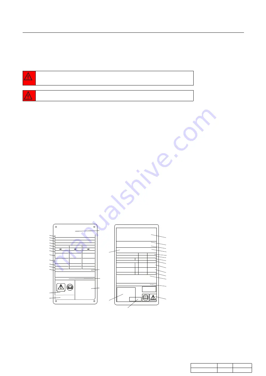
1. Space for logotype
2. Open space
3. Website for service
4. Drawing of possible locations of connections/Location of 3A tag for 3A units
5. Space for mark of approval
6. Warning, read manual
7. Date of pressure test
8. Maximum operating temperature
9. Manufacturer test pressure (PT)
10. Allowable temperatures Min/Max (TS)
11. Allowable pressures Min/Max (PS)
12. Decisive volume or volume for each fluid (V)
13. Locations of the connections for each fluid
14. Decisive fluid group
15. Year of manufacture
16. Serial number
17. Type
18. Manufacturer’s name

1

2

3

4

18

17

16

15

14
13
12
11

10

9
8
7

6

5

1

18

15

13

14
12

8

11

10

9

6

5

4

17

7

3

TS

V

INLET → OUTLET

VOLUME

MIN./MAX.

ALLOWABLE PRESS.

STATISTICAL BASIS.

MANUFACTURER

FOR SERVICE:

PRESSURE TESTING PERFORMED ON

PRESSURE TESTED 

MAX. OP. TEMP.

FLUID GROUP

YEAR OF MANUFACTURING:

MANUFACTURER: 

ALLOWABLE TEMP.

MIN./MAX.

TYPE:

SERIAL NUMBER:

PT

PS

Service

Year

Manufacturer

Fluid group
Inlet            Outlet

Allowable press.

Allowable temp.

Volume                  V

Manufacturer

Serial No.

Type

Max. op. temp.
Test pressure date

WARNING

Min./Max.              PS

Min./Max.    TS

PT

16

Figure 1. Example of CE metallic name plate to the left and CE sticker label name plate to
the right

Document ID

Language

Edition

8

Instruction Manual - Plate Heat Exchangers

3490017599

EN

2016-06

Summary of Contents for FrontLine WideGap 100

Page 1: ...Instruction Manual Plate Heat Exchangers M15 TL10 TL15 T20 TS20 MX25 MA30 WideGap 100 WideGap 200 3490017598 EN 2016 06 Original manual EN IT FI LT...

Page 2: ......

Page 3: ...continually updated on our website Please visit www alfalaval com to access the information directly Alfa Laval Corporate AB This document and its contents is owned by Alfa Laval Corporate AB and pro...

Page 4: ...te NOTE indicates a potentially hazardous situation which if not avoided may result in property damage PHE drawings PHE plate heat exchanger drawings mentioned in the manual are the drawings included...

Page 5: ...changer has been taken out of service for an extensive period of time longer than one year the risk of leakage when starting up increases To avoid this problem it is recommended to let the gasket rubb...

Page 6: ...between frame plate and pressure plate Refer to the PHE drawing 4 Pressure plate Moveable plate that can contain a various number of portholes for the connection of the piping system 5 Guiding bar Kee...

Page 7: ...ds of the tightening bolts Insulation For applications where the heat exchanger surface will be hot or cold insulation can be used Lifting device Separate device that are attached on the heat exchange...

Page 8: ...3 Website for service 4 Drawing of possible locations of connections Location of 3A tag for 3A units 5 Space for mark of approval 6 Warning read manual 7 Date of pressure test 8 Maximum operating tem...

Page 9: ...is assembled between a frame plate and a pressure plate and compressed by tightening bolts The plates are fitted with a gasket which seals the channel and directs the fluids into alternate channels T...

Page 10: ...longer heating periods if the media requires slower heating 1 End plate I 2 End plate II 3 Channel plate 4 Transition plate 5 Turning plate 6 Partition plate 3 3 1 2 4 4 5 5 6 Figure 3 Example of a m...

Page 11: ...ot or aggressive fluids and the hot plate pack If the heat exchanger surface temperature is expected to be hot or cold take protective actions such as insulate the heat exchanger to avoid risk for per...

Page 12: ...ads from the piping system Connections in the pressure plate It is important that the plate pack has been tightened to the correct dimension A check against the PHE drawing before the piping system is...

Page 13: ...and MA30 Raising This instruction is valid when raising the heat exchanger after delivery from Alfa Laval Only use a strap approved for the weight of the heat exchanger Follow the principle of the in...

Page 14: ...ger on the timber beams Step 4 Place straps around one bolt on each side Step 5 Lift the heat exchanger off the timber beams Step 6 Lower the heat exchanger into a horizontal position and place it on...

Page 15: ...started with valves closed and the valves must be operated as smoothly as possible Do not run pumps temporarily empty on the suction side Note Adjustments of flow rates should be made slowly in order...

Page 16: ...pen the valve slowly Note Avoid rapid temperature changes in the heat exchanger With media temperatures over 100 C slowly increase the temperature preferably at least for one hour Step 7 When all the...

Page 17: ...h one should be stopped first Step 1 Slowly close the valve controlling the flow rate of the pump you are about to stop Step 2 When the valve is closed stop the pump Step 3 Repeat Step 1 and Step 2 fo...

Page 18: ...without opening it The purpose of cleaning with CIP is as follows Cleaning of fouling and descaling of lime deposits Passivation of cleaned surfaces to reduce susceptibility to corrosion Neutralizati...

Page 19: ...the total diluted cleaning solution to provide better cleaning results on oily and fatty surfaces and where biological growth occurs AlfaAdd also reduces any foaming If CIP cannot be done cleaning mu...

Page 20: ...Bolt configuration The bolt configuration of the heat exchanger varies between different models The major force of the plate pack is held by the tightening bolts TB To distribute the force evenly ove...

Page 21: ...rom the pressure plate so that the pressure plate are free to move along the carrying bar Step 6 Inspect the sliding surfaces of the carrying bar and wipe clean and grease Step 7 Mark the plate assemb...

Page 22: ...nating between each bolt until all reaction forces of the plate pack have disappeared Then remove the bolts A A 3 1 2 4 Step 11 Open the plate pack by letting the pressure plate glide on the carrying...

Page 23: ...uipment such as safety boots safety gloves and eye protection when using the cleaning agents Warning Corrosive cleaning liquids Can cause serious injuries to skin and eyes Deposits removable with wate...

Page 24: ...cleaning For a choice of cleaning agents refer to Cleaning liquids on page 19 Step 1 Brush with cleaning agent Step 2 Rinse immediately with water Note Long exposure to the cleaning agents can damage...

Page 25: ...the grooves Note If the gasket is wrongly positioned it will show by the fact that it rises out of the gasket groove or that it is positioned outside the groove Step 4 If the plates have been removed...

Page 26: ...e Nm kpm Nm kpm M30 900 90 M39 1300 130 2000 200 M48 2100 210 3300 330 For manual tightening the tightening torque has to be estimated If dimension A cannot be reached Check the number of plates and t...

Page 27: ...s specified on the plate hanging list Use the marked line that was made when the heat exchanger was opened refer to Step 7 in Opening on page 20 Step 5 5 Press the plate pack together and put the tigh...

Page 28: ...ther side open to the ambient pressure When multi pass set up all sections of the same side must be tested simultaneously Caution The pressure testing shall be performed at a pressure equal to the ope...

Page 29: ...p 2 Remove the old gasket Step 3 Make sure that all sealing surfaces are dry clean and free of foreign matter such as fat grease or similar Step 4 Check the gasket and remove rubber residual before at...

Page 30: ...Alfa Laval sales representative Refer to Warranty conditions on page 4 Step 2 Remove the old gasket Step 3 It is not necessary to remove old tape as the film is very thin Make sure however that the ga...

Reviews: