4303-0151
100000818-EN2
2020-02
Original manual
Instruction Manual
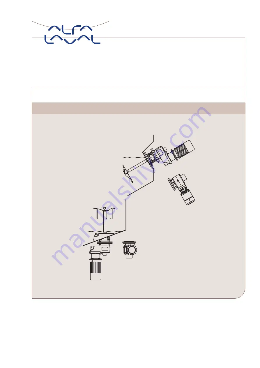
Alfa Laval Agitator - ALS / ALB ATEX
Page 1: ...4303 0151 100000818 EN2 2020 02 Original manual Instruction Manual Alfa Laval Agitator ALS ALB ATEX...
Page 2: ......
Page 3: ...oting 25 4 3 Cleaning recommendations 26 4 4 Temperature limits 26 5 Maintenance 27 5 1 General maintenance 27 5 2 Replacement of drive unit 28 5 3 Replacement of shaft seal type S3 29 6 Technical dat...
Page 4: ...is used DS EN ISO 12100 2011 Safety of Machinery Risk Assessment is in conformity with Ex ATEX Directive 2014 34 EU The following harmonised standards and regulations have been applied for non electri...
Page 5: ...esignation ALT B is for top mounting ALS is for side mounting and ALB is for bottom mounting The exact mounting angle is specified on the Name Plate and must be followed Definitions on mounting angles...
Page 6: ...r start Agitator in the wrong rotation direction Never use the Agitator for hybrid mixture Always rinse well with clean water after cleaning Beware of temperature limitations Beware of Agitator in ope...
Page 7: ...held responsible for incorrect unpacking Step 1 Inspect the delivery for visible transportation damages all issues to be reported to carrier Step 2 Check the delivery for 1 Complete Agitator 2 Namepla...
Page 8: ...tudy the instructions carefully TD605 103 WARNING Do NOT use eye bolts on gear motor to lift the Agitator They are only for gear motor removal TD605 101 WARNING Do NOT use eye bolts on shroud if any t...
Page 9: ...hafts must be supported adequately during lifting to protect shaft bearings and seals arrangements Gear motor motor may be used for lifting the assembled Agitator Step 4 During transportation 1 Always...
Page 10: ...the Agitator see Step 2 Always have safety elements removed by authorized personnel Never cover or remove the nameplate Never connect to power supply during installation or service Always have the Agi...
Page 11: ...uration The following information is required to calculate the forces P Power of the motor in kW n Speed of Agitator shaft RPM S Shaft length according to Agitator type designation Sxxxx in mm D Large...
Page 12: ...stalling Flat Shaped Welding Flange FSWF ALS Agitator for mounting flange without nose CAUTION Alfa Laval recommend that all other welding tasks on the tank are finished before installing welding flan...
Page 13: ...wn on the illustration below In case of installation of Welding Flange parallel to tank bottom surface shaft perpendicular to tank bottom surface it is always recommended to use a bead cone This is to...
Page 14: ...t Welding procedure FSWF ALS Agitator for mounting flange without nose Step 1 Always allow flange to cool to ambient temperature after each section has been welded Position the flange correctly T D 6...
Page 15: ...ation see chapter 3 3 Pre use check The Agitator is for permanent fastening Make sure that the motor correspond to the environment Step 4 Ensure that the surface flatness tolerance equals 0 25 after w...
Page 16: ...lding flange onto a bended rim of the tank bottom plate this is to secure adequate flexibility at high loads e g when the tank is filled If a bended rim is impossible to obtain due to a high plate thi...
Page 17: ...to the environment Step 4 Weld the following sections first from inside then from outside and cool to ambient temperature after each section has been welded Step 1 Step 2 Step 3 TD605 217 A B C D E F...
Page 18: ...side mounted Agitator type ALS and chapter 6 3 Mounting angle for bottom mounted Agitator type ALB Always refer to tightening torques in chapter 6 5 Tightening torques for bolt connections when tight...
Page 19: ...ment Step 3 Mount impeller device s onto shaft Hub diameter mm a dimension mm 30 1 1 40 1 8 55 80 120 2 8 TD605 037 3 x 3 x TD605 038 a a All weld propeller to shaft with one welding seam at a time co...
Page 20: ...installation requirements regarding the position can be found in chapter 6 2 Mounting angle for side mounted Agitator type ALS and chapter 6 3 Mounting angle for bottom mounted Agitator type ALB to e...
Page 21: ...which deviate from those given in chapter 2 3 Intended use and 6 1 Technical data Always ensure that all alignment specifications given in chapter 6 6 Shaft alignment are followed Always make sure th...
Page 22: ...s used the speed must be monitored according to section 6 7 Use of frequency converter drive VLT It must be ensured NOT to operate continuously within 20 of critical oscillation speed The critical osc...
Page 23: ...incineration plant Metal straps should be sent for material recycling Maintenance During maintenance oil and wear parts in the machine are replaced All metal parts should be sent for material recyclin...
Page 24: ...itch off the Agitator and find the cause of failure see chapter 4 2 Troubleshooting The Agitator is designed to max 5 starts per hour Inspect the Agitator regularly Inspect Clean Lubricate Supplier in...
Page 25: ...ased temperature Unusual noise Defect Replace drive unit Bearing gap Renovate or change the drive unit immediately Increased decreased power Switch of power supply Drive unit No grease Replace drive u...
Page 26: ...ning In Place SIP Sterilising In Place Always rinse well with clean water after cleaning 4 4 Temperature limits The highest allowable ambient temperature is 40 C The highest allowable operating temper...
Page 27: ...e proper tools Always replace sealing elements before reassembling WARNING Follow the dismantling and assembly instructions to the letter After maintenance chapter 3 3 Pre use check must be read thoro...
Page 28: ...ismantling drive unit please see instructions in 5 3 Replacement of shaft seal type S3 Step 3 Loosen cap nuts CAUTION If dismantling motor from gear Follow supplier instructions Ensure that the gear o...
Page 29: ...all seal faces are totally clean using alcohol If possible always dismantle the Agitator from the tank before dismounting any parts The seal see chapter 2 3 Intended use is designed for dry running s...
Page 30: ...s in chapter 6 1 Technical data Step 3 1 Remove guards from lantern 2 Remover cap nuts 3 Move the mounting flange including stationary seal ring carefully along the shaft avoiding contact TD605 092 1...
Page 31: ...tator type ALS To ensure optimal agitation the side mounted Agitator must be installed in the mounting angle specified on the name plate as described in the Alfa Laval quotation agreement and as shown...
Page 32: ...nting angle for bottom mounted Agitator type ALB To ensure optimal agitation the bottom mounted Agitator must be installed in the mounting angle specified on the name plate as described in the Alfa La...
Page 33: ...ator and depending on the zone classification inside the tank the level switch must correspond to different safety levels Zone 0 20 inside the tank the level switch must correspond to b2 according to...
Page 34: ...fter propellers has been welded onto the shaft and or two shaft parts has been welded together the shaft must be aligned If the shafts has been welded according to Alfa Lavals recommendations shown be...
Page 35: ...est of the shaft and the surrounding temperature 2 10 minutes depending on amount of heat introduced 6 Step 3 4 and 5 are repeated until the alignment is according the specified U which is a function...
Page 36: ...hall be evaluated and may marked b2 according to EN ISO 80079 37 6 The functions of these ignition protective systems have to be checked before start up according to the manual from the manufacturer o...
Page 37: ...6 Technical data 6 8 Storage Store the Agitator in dry and clean environments Rotate shaft every second week to ensure seal faces do not stick together 37...
Page 38: ...7 Parts list and drawing service kits 7 1 Agitator ALS ALB ATEX 4303 0152 4303 0156 4303 0155 38...
Page 39: ...ivet 130 1 Parallel key 142 1 Welding flange 143 1 Welding flange 144 1 Welding flange raised 146 1 Fixing element 147 1 Screw 157 1 Spring ring 158 2 Guard 159 8 Screw 160 8 Cap nut Service kits Deno...
Page 40: ...ng maintenance and storage of the drive unit please find the drive unit instruction manual by below links For Agitators with gears please find the drive unit instruction manual by below link https www...
Page 41: ...41...
Page 42: ...s the responsibility of the user of this document to comply with all applicable intellectual property laws Without limiting any rights related to this document no part of this document may be copied r...