


............................................................................................................................................................................................................................................................
DS1 cable installation
Equipment and cable installation for 1665 Data Multiplexer
(1665 DMX)
1 - 3 4
365-372-304R7.1
Issue 1, November 2007
............................................................................................................................................................................................................................................................
DS1 cable installation
Description
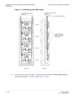
This section describes how to connect the DS1 transmission cables to the shelf, route the
cables out of the bay and connect the cables to the DSX. Perform this procedure if DS1
cables are required.
Important!
When cabling the 1665 DMX High-Capacity shelf to a DSX, the DSX
becomes an extension of the 1665 DMX High-Capacity shelf backplane connections.
Thus the IN on the 1665 DMX High-Capacity shelf backplane connects to the IN of
the DSX and the OUT of the 1665 DMX High-Capacity shelf backplane connects to
the OUT of the DSX respectively.
The cables are connectorized at the 1665 DMX High-Capacity shelf end and must be
wire-wrapped at the DSX end. A total of four function groups fully cabled will have 224
DS1 drop capacity when the higher density DS1 circuit packs become available.
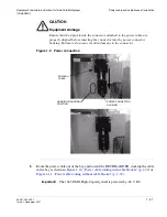
Important!
The connectorized cable end is grounded to the 1665 Data Multiplexer
(1665 DMX) frame ground through the backplane. Alcatel-Lucent recommends that
the shield at both ends of the cable be grounded. Ground at the DSX end per office
requirements.
Procedure
Proceed as follows:
........................................................................................................................................................................................................................
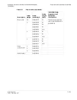
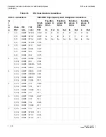
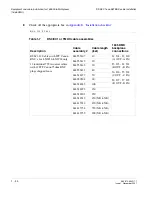
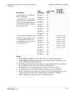
1
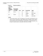
Refer to the engineering job specification. Obtain the DS1 cables per
and note the function group where each cable will be used.
Label the cables, indicating bay, shelf, function group (A, B, C or D) and direction (IN or
OUT of the bay) at each end.
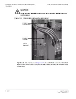
Important!
The first 28 DS1s of a Function Group, must be connected to the bottom
connectors (J1- J8). The additional capacity (28 additional DS1s, 29-56) of the
Function Group use the connectors located in the middle of the backplane (J20 - J27).
Summary of Contents for Data Multiplexer Explore 1665
Page 8: ... Contents v i i i 365 372 304R7 1 Issue 1 November 2007 ...
Page 12: ... List of figures x i i 365 372 304R7 1 Issue 1 November 2007 ...
Page 16: ... List of tables x v i 365 372 304R7 1 Issue 1 November 2007 ...
Page 24: ... About this document x x i v 365 372 304R7 1 Issue 1 November 2007 ...
Page 272: ... Final operations Operational tests 5 2 2 365 372 304R7 1 Issue 1 November 2007 ...
Page 326: ... Cleaning pluggable optics modules Fiber cleaning B 1 4 365 372 304R7 1 Issue 1 November 2007 ...
Page 408: ...I N 4 365 372 304R7 1 Issue 1 November 2007 Index ...