


............................................................................................................................................................................................................................................................
Fiber installation
Ring setup and testing: integration procedures
6 - 6
365-372-304R7.1
Issue 1, November 2007
Important!
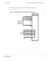
For 1665 DMX ring configurations, optical fibers extend in two different
directions to make up the ring. At each shelf (node) in the ring, the
M1
OLIU will
connect to the
M2
OLIU in one adjacent node, and the
M2
OLIU will connect to the
M1
OLIU in the other adjacent node. Likewise, when the 1665 DMX is interfacing
with other equipment at low-speeds (OC-3, OC-12 or OC-48) using 0x1 protection,
the Function Group slot (A, B, C, D, or G)
1
will connect to
Main 2
on whatever shelf
the 1665 DMX is being connected to. The Function Group slot (A, B, C, D, or G)
2
will connect to
Main 1
.
........................................................................................................................................................................................................................
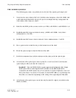
10
At each end of the optical span, connect the optical fiber transmit cables to the OLIU OUT
connectors.
........................................................................................................................................................................................................................
11
At each end of the optical span, measure the optical power of the optical fiber receive
cables using an optical power meter.
........................................................................................................................................................................................................................
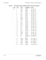
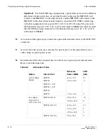
12
Determine the LBO value required based on the received optical power measurement.
Refer to the following table.
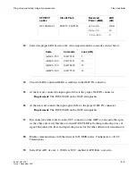
Table 6-1
Attenuation Table
Optics
Circuit Pack
Received
Power (dBM)
LBO
(dB)
OC-48 (High
Speed)
LNW27
LNW29
LNW221 - 259
LNW421 - 459
LNW32
+3.0 to -9.0
-9.0 to -29.0
15
0
LNW76 -3.0
to
-18.0
0
Low-Speed
Optics (OC-3,
OC-12, OC-48)
LNW36 (OC-3)
0.0 to -15.0
10
-15.0 to -34.0
0
LNW46 (OC-12)
+2.0 to -8.0
10
-8.0 to -15.0
5
-15.0 to -30.5
0
LNW31 (OC-48)
0.0 to -18.0
0
Summary of Contents for Data Multiplexer Explore 1665
Page 8: ... Contents v i i i 365 372 304R7 1 Issue 1 November 2007 ...
Page 12: ... List of figures x i i 365 372 304R7 1 Issue 1 November 2007 ...
Page 16: ... List of tables x v i 365 372 304R7 1 Issue 1 November 2007 ...
Page 24: ... About this document x x i v 365 372 304R7 1 Issue 1 November 2007 ...
Page 272: ... Final operations Operational tests 5 2 2 365 372 304R7 1 Issue 1 November 2007 ...
Page 326: ... Cleaning pluggable optics modules Fiber cleaning B 1 4 365 372 304R7 1 Issue 1 November 2007 ...
Page 408: ...I N 4 365 372 304R7 1 Issue 1 November 2007 Index ...