


4. Installation of the Components
143
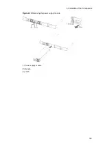
[Step 2]
Mount the EPU into the rack.
Figure 4-10
Mounting into the rack
(1) M5 screws (4)
(2) 19-inch cabinet rack
When mounting the device on a rack, check thoroughly that the device is in a stable
condition. Otherwise, the switch might fall or the rack might tip over, which could
result in serious injury.
NOTE
When mounting the device into a rack, use the M5 screws supplied with the rack.
4.4.3 Inserting and removing power supply modules
CAUTION
Prior to mounting/dismounting the power supply module, turn off the switch of it.
NOTE
The figures below show how to insert and remove a power supply module to and
from slot 2 of the external power unit EPU-A. The same procedures are applicable
to the other slots of EPU-A as well as EPU-B.
(1) Installing
Insert the power supply module until you hear a click.
Summary of Contents for AX2400S series
Page 3: ...Copyright Copyright C 2005 2011 ALAXALA Networks Corporation All rights reserved ...
Page 4: ......
Page 6: ...Preface II Find description from the AX2400S series manuals ...
Page 7: ...Preface III Find description from the AX3640S and AX3630S series manuals ...
Page 10: ...Preface VI ...
Page 14: ...Contents iv ...
Page 160: ...3 Preparation of Interface Cables and Terminals 130 ...


