ADDENDUM
NEW KEY LOGGING FEATURE
WI1587 1/07
The new
Key Logging
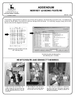
feature creates an entry in the Audit Log when a conventional key is used for entry. Two sample log
entries are shown below, one printed, the other as displayed in DL-Windows. To enable Key Logging, simply connect the
wires as shown in the images at the bottom.
345 Bayview Avenue
Amityville, New York 11701
For Sales and Repairs 1-800-ALA-LOCK
For Technical Service 1-800-645-9440
Publicly traded on NASDAQ Symbol: NSSC
© ALARM LOCK 2007
HOW TO ROUTE AND CONNECT THE WIRES
1. Route wires through door as shown. The
cylinder housing has two terminal housings,
and each housing contains two wires -- one
housing contains
red/black
wires, the other
black/black
.
------- AUDIT LOG -------
01/16/07 13:06:35 Tue
13:01:59 001 PROGRAM 56
13:01:29 001 PROGRAM 57
13:00:53 001 ENTRY
13:00:26 013 ENTRY
13:00:17 KEY ENTRY
13:00:03 012 ENTRY
12:56:27 001 PROGRAM 2
12:56:27 001 PROGRAM 40
12:56:04 001 PROGRAM 39
12:55:00 NEW CLCK TIME
12:01:39 OLD CLCK TIME
12:00:45 RAM TEST:PASS
12:00:45 POWER UP
-------------------------
End of Audit Log
Sample log entry printed by the AL-
IR1 infrared printer.
Sample log entry as displayed by
DL-Windows (v3.6.0 or later).
Be sure two wires
are side-by-side
and do not overlap
2. After installing the inside housing, be
certain wires are not pinched between
the housing and the mounting plate.
Hold-down
clamp
3. Plug in each pair of connectors. Verify that the
wire colors in each pair of female and male terminal
housings are the same --
red/black
to
red/black
and
black/black
to
black/black
.
Red/Black
to
Red/Black
Black/Black
to
Black/Black
Red/
black
wires
Black/
black
wires

