GB
30
MH540 | MH770 | MH1150
Start-up
4.2.6
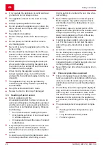
Installing the gear lever (15)
1. Screw the handle (15/1) onto the gear lever
(15/2).
4.2.7
Installing the clutch lever (16)
1. Insert the clutch lever (16/1) with threaded
pins through the holes on the handlebar
(16/2).
2. Fit nuts (16/3) and tighten.
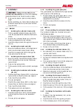
4.2.8
Installing guard plates (17)
The guard plates are installed to the right and left
of the engine in the same way.
1. Position (17/a) the guard plate (17/1) on the
holding plate (17/2) so that the holes are
aligned with one another.
2. Position cross struts (17/3) from below onto
the guard plates.
3. Insert the bolts from above through the holes.
4. Fit nuts and tighten.
4.3
MH1150
4.3.1
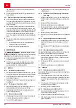
Preassembling the cultivator blades
(19)
Four cultivator blades are mounted onto each
shaft fastening plate.
1. Place two cultivator blades (19/1) on each
side of the fastening plate (19/2). In the pro-
cess, position each cultivator blade offset by
90° to the next blade.
2. Insert four bolts (19/3) through the holes in
the cultivator blade and fastening plate.
3. Screw on the nut (19/4).
4.3.2
Installing the cultivator blades (20)
1. On both sides, fit a cultivator blade set (20/1)
onto the axle mount.
2. Fit additional cultivator blade sets.
3. Connect all cultivator blade sets together with
clip pins.
4. Fit a protective disc (20/2) on both sides and
secure using a clip pin on each.
4.3.3
Installing the depth skid (21)
1. Insert the fastening sleeve of the depth skid
(21/1) into the base carrier (21/2) (21/a).
2. Slide the locking pin (21/3) through the hole
and secure with spring split pin.
4.3.4
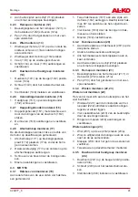
Fitting the impellers (22, 23)
Preassembling the impellers (22)
The valve must be located on the outside of the
impeller.
1. Align wheel hub (22/1) on the inside of the
impeller (22/2) so that the holes are aligned.
2. Insert four hexagon bolts (22/3) through the
holes from the outside.
3. Fit the washers and nuts (22/4) and tighten.
Fitting the impellers (23)
1. Place the impeller (23/1) onto the axis (23/2)
(23/a).
2. Align the impeller until the holes on the wheel
hub and axis are aligned.
3. Insert the clip pin (23/3) through the hole and
secure.
4. Install the second impeller in the same way.
4.3.5
Installing the handlebar with handle
(24)
1. Position (24/a) the handlebar (24/1) on the
base carrier (24/2).
2. Insert the bolt (24/3) through the grid joint.
3. Fit the clamping lever (24/4) and tighten.
4.3.6
Installing the gear lever (25)
1. Screw the handle (25/1) onto the gear lever
(25/2).
4.3.7
Installing the clutch lever (26)
1. Insert the clutch lever (26/1) with threaded
pins through the holes on the handlebar
(26/2).
2. Fit nuts (26/3) and tighten.
4.3.8
Installing the guard plate (27, 28)
1. Place the front cross beam (27/1) centrally on
the base carrier (27/2) so that the holes are
aligned.
2. Fully insert the hexagon bolt and tighten nut.
3. Place rear cross beams (27/3) on the right
and left of the base carrier.
4. Fully insert the hexagon bolt and tighten nut.
5. Place the guard plates (28/1) on the cross
beams (28/2).
6. Insert bolts with washers from above through
the guard plate and cross beams.
7. Fit nuts from below and tighten.
5
START-UP
5.1
Adjusting the handlebar MH770, MH1150
(29)
Adjust the height of the handlebar
The normal height adjustment corresponds to hip
height.


