Akytec SMI200 User Manual Download Page 8


Display and function buttons 


akYtec GmbH · Vahrenwalder Str. 269 A · 30179 Hannover · Germany · Tel.: +49 (0) 511 16 59 672-0 · www.akytec.de  


7


5  Display and function buttons 

The device and process parameters can be viewed and edited (if available) on the display using 
the function buttons. For device parameters, see section 6 “System menu”. 

To view or edit the process parameters, display forms have to be programmed with different dis-
play elements. Jump conditions have to be created to let an operator to switch between the display 
forms using the function buttons. Jump condition can be a button event of a variable event. For 
further details about display elements and jump conditions use Help in akYtec ALP. 

There are editable and not editable display elements thus the display can be used in view or edit 
mode. 

In the view mode (default): 


use 

 and 

 buttons to move between lines 


use 

 button to enter the selected level, and 

 button to exit it 

To edit the parameter, press the button 

. The first editable element on the display starts flash-

ing. Use 

 and 

 buttons to change the value. Use the button combinations to move between 

characters: 


 + 

 – one character to the left 


 + 

 – one character to the right 

To save the new value and edit the next parameter, use the button 

To reset the parameter to its previous value and exit the edit mode, use the button 

To save the new value staying in the edit mode, use the button 

. The next editable parameter 

will be displayed selected. 

The last changed parameter will be shown next time when the edit mode is active. 

Note: 

When assigning а jump condition to the function button, don't forget that the user function will have 

a higher priority than the system function. 

Example: 

If the 

 and 

 buttons are used as a jump condition for a certain display, it will be impossible to 

use them to scroll the lines inside this display. 

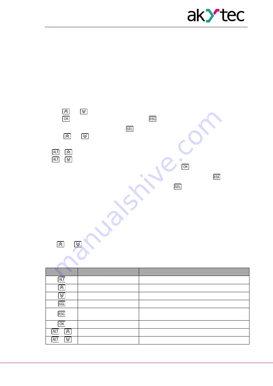
Table 5.1   Function buttons 

Button 

View 

Edit 


open system menu (>3 s) 


one line up 

increase value 


one line down 

decrease value 


activate edit mode 

save the new value and edit the next parameter 


exit level / 
exit system menu (>3 s) 

reset the parameter to its previous value and exit 
the edit mode 


enter selected level 

save the new value and exit the edit mode 

 + 


one character to the left 

 + 


one character to the right 

Summary of Contents for SMI200

Page 1: ...enwalder Str 269 A 30179 Hannover Germany Tel 49 0 511 16 59 672 0 www akytec de SMI200 Programmable compact controller User guide SMI200_2019 06_ 0275 _EN All rights reserved Subject to technical changes and misprints ...

Page 2: ...sign 2 2 Specifications 3 2 1 Environmental conditions 3 3 Safety 4 3 1 Safety symbols and key words 4 3 2 Intended use 4 4 Installation 5 4 1 Safety precautions 5 4 2 Wiring 5 5 Display and function buttons 7 6 System menu 8 7 Operation 10 7 1 RUN STOP 10 7 2 Down Mode 11 8 Maintenance 12 9 Transportation and storage 13 10 Scope of delivery 14 ...

Page 3: ...e connection with akYtec ALP running on the PC can be established over the USB interface Fig 1 1 When being connected to PC over USB the device is powered by USB and does not need additional power supply User application includes the logic program created as a function plan as well as the device config uration 1 1 Functions The device has the following basic functions 2 line 32 character LCD displ...

Page 4: ...ery CR1025 Mechanical IP code IP54 front IP20 rear Dimensions with terminal block 100 x 60 x 60 mm Weight approx 150 g EMC safety EMC immunity conforms to IEC 61326 1 A1 EMC emission conforms to EN 55011 A1 The limitation applies only to the slave mode in which all network variables are automatically declared as retain 2 1 Environmental conditions The module is designed for natural convection cool...

Page 5: ...derate injury NOTICE NOTICE indicates a potentially harmful situation which if not avoided may result in dam age of the product itself or of adjacent objects 3 2 Intended use The device is provided only for the areas of application described in this user guide when all indi cated specifications are observed The device can be used only according to the data given in the specification Improper use A...

Page 6: ...4 1 Safety precautions DANGER Ensure that the mains voltage matches the voltage marked on the nameplate Ensure that the device is provided with its own power supply line and electric fuse NOTICE Switch off the power supply before working on the device Switch on the power supply only after completing the work EMC safety Signal cables should be routed separately or screened from the supply cables Sh...

Page 7: ...Installation akYtec GmbH Vahrenwalder Str 269 A 30179 Hannover Germany Tel 49 0 511 16 59 672 0 www akytec de 6 Maximum wire cross section is 1 0 mm Fig 4 4 ...

Page 8: ...ts flash ing Use and buttons to change the value Use the button combinations to move between characters one character to the left one character to the right To save the new value and edit the next parameter use the button To reset the parameter to its previous value and exit the edit mode use the button To save the new value staying in the edit mode use the button The next editable parameter will ...

Page 9: ...ave Fig 6 3 Protocol Modbus Master The structure of the system menu depends on the interface configuration in ALP as a master or a slave MENU Device 3 s 3 s Password Interface COM1 Settings Baud rate Data bits Parity Stop bits see Fig 6 2 6 3 Protocol Version Device and firmware version Display Backlight timeout Brightness Contrast Time Date Correction Cycle time Clock Program Run Stop ALT ESC OK ...

Page 10: ...an be interrupted using the menu item Device Program Run Stop The device must be restarted for the change to take effect The menu can be password protected although there is no password by default The password can be set or changed with ALP or using the system menu If the password is lost it can be changed or deactivated by loading a new application ...

Page 11: ...Program STOPPED Application stopped Start the application using system menu and restart the device Table 7 2 Modbus registers Parameter Data type Address Read function Write function Network variables BOOL 0x2000 0x23F0 0x01 0x02 0x05 0x0F INT16 0x0200 0x023F 0x03 0x04 0x06 0x10 Seconds INT16 0x0400 0x03 0x04 0x06 0x10 Minutes INT16 0x0401 0x03 0x04 0x06 0x10 Hours INT16 0x0402 0x03 0x04 0x06 0x10...

Page 12: ...7 2 Down Mode In this mode the firmware update can be forced This mode is necessary to repair the firmware if the last firmware update was unsuccessful power outage transmission error etc See ALP Help for further details about firmware update To activate the Down Mode power on the device with the button pressed ...

Page 13: ...ng of the housing and terminal blocks from dust dirt and debris checking the fastening of the device checking the wiring connecting leads fastenings mechanical damage The device should be cleaned with a damp cloth only No abrasives or solvent containing cleaners may be used The safety information in section 3 must be observed when carrying out mainte nance ...

Page 14: ...ter delivery into operation it must be carefully stored at a protected location The device should not be stored in an atmosphere with chemically active sub stances Permitted storage temperature 20 55 C NOTICE Transport damage completeness The device may have been damaged during transportation Check the device for transport damage and completeness Report the transport damage immediately to the ship...

Page 15: ...Scope of delivery akYtec GmbH Vahrenwalder Str 269 A 30179 Hannover Germany Tel 49 0 511 16 59 672 0 www akytec de 14 10 Scope of delivery SMI200 1 Gasket 1 Mounting nut 1 Terminal block 1 Short guide 1 ...

Reviews: