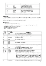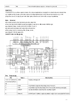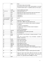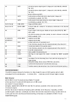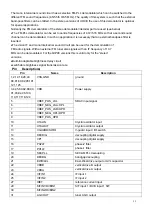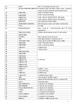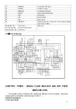
14
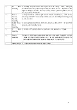
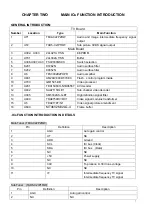
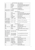
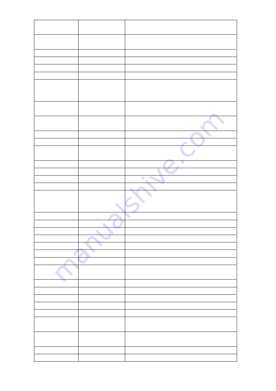
4,14,22,30
38,46,165
OGND
Video port output
ground
7
,
8
,
9
,
10
,
15
,
16
,
17
,
18
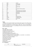
VPA0~VPA7 Video
port
A
11,116,130,132
VDDC
Power supply port
12,117,159 CGND
Ground
23~28,31,32
VPB0~VPB7
Video port B
35,36,39~44
VPC0~VPC7
Video port C
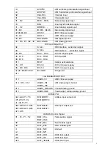
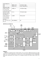
47,53,57,58,55
60,66,70,71,75
81,83,85,86,
AGND Analog
ground
48,54,59,61,67
69,76,82,85,87,88
VDDA
Power supply port
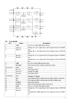
49 REFB/Pb
Blue/blue-chrominance channel reference input
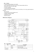
52,51,50 B/Pb1~
B/Pb3
Blue/blue-chrominance channel analog input
56 BIAS
Bias
input
62
REFG/Y
Green/green-chrominance channel reference
input
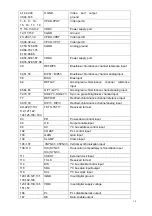
65,64,63 G/Y1~G/Y3
Green/green-chrominance channel analog input
74,73,72 SOG/Y1~SOG/Y3
Sync
on
green//brightness channel input
77 REFR/Pr
Red/red-chrominance channel reference input
80,79,78 R/Pr1~
R/Pr3
Red/red-chrominance channel analog input
89~92,97~101
112,121,122,
124,125,160~163
TST0~TST17
Reserved for test
93
PD
Power-down control input
94
OE
Output enable input
96
A0
I²C bus address control input
102
COAST
PLL control input
103 GAIN Gain
input
104 CLAMP
Clamp
input
105~107 VSYNC1~VSYNC3 Vertical
synchronization input
108~110 H(C)SYNC1~
H(C)SYNC3
Horizontal (composite)synchronization input
111
CKEXT
External clock input
113
TCLK
Reserved for test
114
DIS
I²C bus disable control input
118
SDA
I²C bus data input/output
119
SCL
I²C bus clock input
120,126,127,131
133,142,148,
IGND
Input digital ground
123,138,139,145
151,157
VDDI
Input digital supply voltage
166
PL
PLL disable belock
output
167
DE
Data enable output


