background image

SERVICE  MANUAL

DA

TA

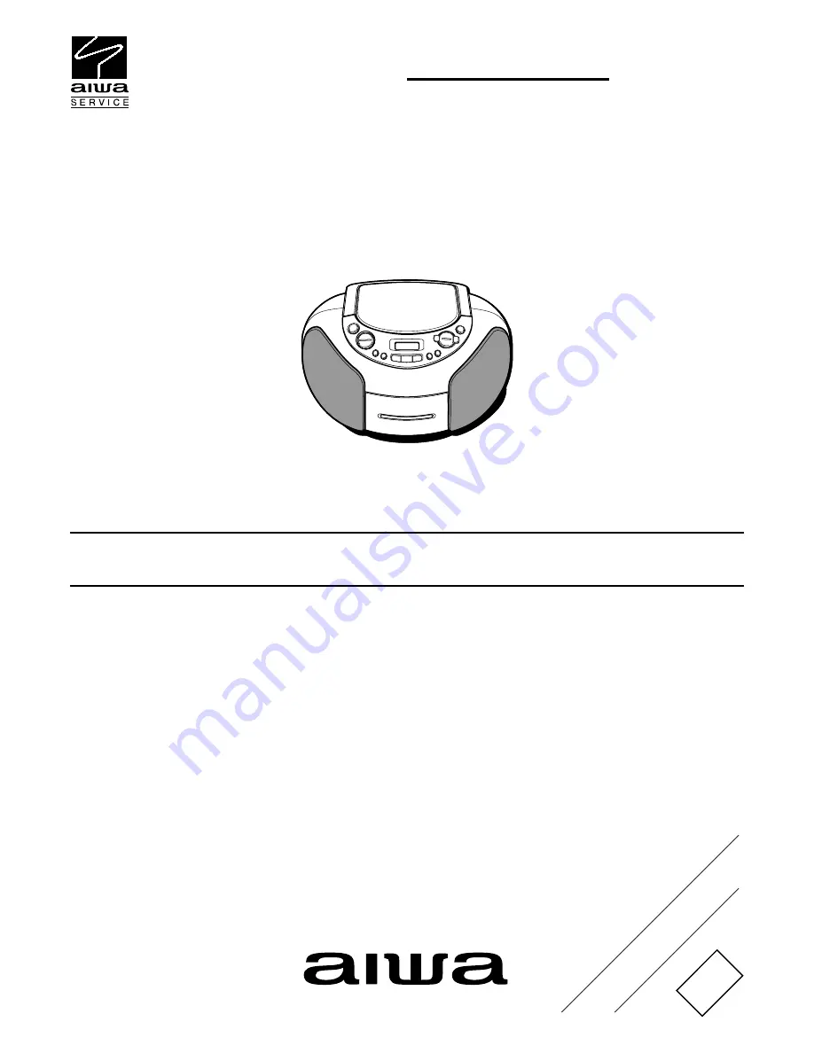
CSD-TD49

LH(W,S,L),
U(W,L),
UC(W)

S/M Code No. 09-027-458-6R1

REVISION

This Service Manual is the “Revision Publishing” and replaces “Simple Manual”
(S/M Code No.09-027-458-6T1)

CD STEREO RADIO

CASSETTE RECORDER

BASIC TAPE MECHANISM:AZM-6 YR3NC
BASIC CD MECHANISM :KSM-213 RDM

Summary of Contents for CSD-TD49

Page 1: ... W L UC W S M Code No 09 027 458 6R1 REVISION This Service Manual is the Revision Publishing and replaces Simple Manual S M Code No 09 027 458 6T1 CD STEREO RADIO CASSETTE RECORDER BASIC TAPE MECHANISM AZM 6 YR3NC BASIC CD MECHANISM KSM 213 RDM ...

Page 2: ...5 FRONT REMOCON DECK 25 WIRING 2 5 FRONT REMOCON 26 SCHEMATIC DIAGRAM 4 5 TUNER 27 WIRING 3 5 TUNER 28 SCHEMATIC DIAGRAM 5 5 POWER BATT 29 WIRING 4 5 POWER BATT 30 WIRING 5 5 DECK 31 VOLTAGECHART 32 33 LCD DIAGRAM 34 ELECTRICAL ADJUSTMENT 35 39 CD TEST MODE 40 IC BLOCK DIAGRAM 41 IC DESCRIPTION 42 45 MECHANICAL EXPLODED VIEW 46 MECHANICAL PARTS LIST 47 48 COLOR NAME TABLE 49 MECHANISM EXPLODED VIE...

Page 3: ...eneral UC U Speaker 80 mm cone type 2 Output Headphones jack stereo mini jack Power output 2 5 W 2 5 W EIAJ 7 ohms THD 10 DC Power requirements DC 12 V using eight size C R14 batteries AC 120 V 60 Hz Power consumption 16 W Dimensions W H D 306 155 253 mm 12 1 8 6 1 8 10 in Weight excluding batteries 2 5 kg 5 lbs 8 oz General LH Speaker 80 mm cone type 2 Output Headphones jack stereo mini jack Powe...

Page 4: ... 4 PROTECTION OF EYES FROM LASER BEAM DURING SERVICING 1 1 ...

Page 5: ...13 RDM 1 1 1 After the connection remove solder shown in the right figure Body or clothes electrostatic potential could ruin laser diode in the optical block Be sure ground body and workbench and use care the clothes do not touch the diode Solder ...

Page 6: ...esignated as spare parts for after sales service and will not be stocked at the spare parts centers UNIT NAME C REF NO PARTS NO PARTS NAME SUFFIX MODEL 6 ACCESSORIES PARTS LIST 1 1 CSD TD49 CSD TD49 CSD TD49 CSD TD49 CSD TD49 CSD TD49 ULC UWC LHLC LHSC LHWC UCWC X AS1001 87 A80 109 010 AC CORD HK7281 BLK U a b f O AS1002 87 A80 187 010 AC CORD SET ASSY BRAZ BLK c d e O AS1003 87 A91 017 010 PLUG C...

Page 7: ...C CAP U 0 1 25 Z F CM CB a b c d e f CD O C 0416 87 010 403 080 CAP E 3 3 50 M 11L SME a b c d e f CD O C 0417 87 010 759 080 C CAP U 0 1 25 Z F CM CB a b c d e f CD O C 0418 87 A10 504 080 C CAP U 0 047 16 K B a b c d e f CD O C 0419 87 010 403 080 CAP E 3 3 50 M 11L SME a b c d e f CD O C 0420 87 010 759 080 C CAP U 0 1 25 Z F CM CB a b c d e f CSD TD49 CSD TD49 CSD TD49 CSD TD49 CSD TD49 CSD TD...

Page 8: ... d e f CD S Q 0105 87 026 462 080 TR 2SC1740SRS a b c d e f CD S Q 0243 87 026 610 080 TR KTC3198GR a b c d e f CD S Q 0244 87 026 610 080 TR KTC3198GR a b c d e f CD S Q 0401 89 112 965 080 TR 2SA1296GR a b c d e f CD S Q 0402 87 026 215 080 TR DTC114YS a b c d e f CD S Q 0407 87 026 610 080 TR KTC3198GR a b c d e f CSD TD49 CSD TD49 CSD TD49 CSD TD49 CSD TD49 CSD TD49 ULC UWC LHLC LHSC LHWC UCWC...

Page 9: ...D X R 0465 88 121 101 080 RES 100 1 8W J a b c d e f CD X R 0466 88 121 392 080 RES 3 9K 1 8W J a b c d e f CD O R 0470 88 108 103 080 C RES U 10K 1 16W J a b c d e f CD O R 0476 88 108 101 080 C RES U 100 1 16W J a b c d e f CD O R 0477 88 108 101 080 C RES U 100 1 16W J a b c d e f CSD TD49 CSD TD49 CSD TD49 CSD TD49 CSD TD49 CSD TD49 ULC UWC LHLC LHSC LHWC UCWC CD O R 0478 88 108 101 080 C RES ...

Page 10: ...95 a b c d e f FRONT X JR 0151 88 108 000 080 C JUMPER U a b c d e f FRONT X JR 0601 88 108 000 080 C JUMPER U a b c d e f FRONT X JR 0602 88 108 000 080 C JUMPER U a b c d e f FRONT X JR 0603 88 108 000 080 C JUMPER U a b c d e f FRONT X JR 0604 88 108 000 080 C JUMPER U a b c d e f FRONT X JR 0605 88 108 000 080 C JUMPER U a b c d e f FRONT X JR 0606 88 108 000 080 C JUMPER U a b c d e f FRONT X...

Page 11: ... RES U 10K 1 16W J a b c d e f FRONT X R 0647 88 108 333 080 C RES U 33K 1 16W J a b c d e f FRONT X R 0648 88 108 334 080 C RES U 330K 1 16W J a b c d e f FRONT O R 0651 88 108 101 080 C RES U 100 1 16W J a b c d e f FRONT O R 0652 88 108 101 080 C RES U 100 1 16W J a b c d e f FRONT O R 0653 88 108 101 080 C RES U 100 1 16W J a b c d e f FRONT O R 0654 88 108 101 080 C RES U 100 1 16W J a b c d ...

Page 12: ... C 0242 87 010 400 080 CAP E 0 47 50 M 11L SME a b c d e f MAIN O C 0243 87 010 401 080 CAP E 1 50 M 11L SME a b c d e f MAIN O C 0244 87 010 401 080 CAP E 1 50 M 11L SME a b c d e f MAIN O C 0289 87 012 199 080 C CAP U 220P 50 J CH GRM a b c d e f MAIN O C 0290 87 012 199 080 C CAP U 220P 50 J CH GRM a b c d e f MAIN O C 0305 87 010 375 080 CAP E 330 10 M 11L SME a b c d e f MAIN O C 0306 87 010 ...

Page 13: ...J a b c d e f MAIN X R 0362 88 108 333 080 C RES U 33K 1 16W J a b c d e f MAIN O R 0363 88 108 822 080 C RES U 8 2K 1 16W J a b c d e f MAIN O R 0364 88 108 822 080 C RES U 8 2K 1 16W J a b c d e f MAIN X R 0367 88 108 682 080 C RES U 6 8K 1 16W J a b c d e f MAIN X R 0368 88 108 682 080 C RES U 6 8K 1 16W J a b c d e f MAIN X R 0381 88 100 000 010 PLATING JW 0 58 SN95 a b c d e f CSD TD49 CSD TD...

Page 14: ...POWER O PT 0701 8C CHB 622 010 PT U CCHB a b f POWER O PT 0701 8C CHB 624 010 PT H CCHB c d e POWER O S 0101 87 A91 370 010 SW AC SL2 2 2 SWS2202 c d e POWER X W 0001 8C CHB 652 010 WIRE RED POWER AC a b c d e f POWER X W 0002 8C CHB 653 010 WIRE ORANGE POWER AC a b c d e f CSD TD49 CSD TD49 CSD TD49 CSD TD49 CSD TD49 CSD TD49 ULC UWC LHLC LHSC LHWC UCWC POWER X W 0003 8C CHB 654 010 WIRE YELLOW P...

Page 15: ... UP050 a b c d e f TUNER O CF 0002 87 A91 729 110 FLTR SFE10 7 MS2C20 A a b c d e f TUNER O CF 0003 87 A91 730 110 FLTR CDA10 7 MG77A A a b c d e f TUNER O CF 0010 87 A91 728 110 FLTR KIT KMFC5184 A a b c d e f TUNER O CN 0001 87 A60 621 010 CONN 4P V 2MM JMT a b c d e f TUNER O CN 0002 87 A60 624 010 CONN 7P V 2MM JMT a b c d e f TUNER X CN 0003 8Z CT4 623 010 PIN TESTDIA0 9 10 a b c d e f TUNER ...

Page 16: ...0 C RES U 100K 1 16W J a b c d e f TUNER X R 0015 88 108 221 080 C RES U 220 1 16W J a b c d e f TUNER O R 0016 88 108 473 080 C RES U 47K 1 16W J a b c d e f TUNER X R 0017 88 108 222 080 C RES U 2 2K 1 16W J a b c d e f TUNER X R 0018 88 108 222 080 C RES U 2 2K 1 16W J a b c d e f TUNER X R 0019 88 108 472 080 C RES U 4 7K 1 16W J a b c d e f TUNER X R 0020 88 108 000 080 C JUMPER U a b c d e f...

Page 17: ...re parts centers Components marked X and R are not designated as spare parts for after sales service and will not be stocked at the spare parts centers UNIT NAME C REF NO PARTS NO PARTS NAME SUFFIX MODEL 17 ELECTRICAL PARTS LIST 11 12 AZM 6 1 1 AZM 6 YR3NC DECK O CN 1 87 A61 731 010 CONN 07P H 621600711 a DECK O CRD1 8A ZM6 603 010 RBN CORD 2P 75 a DECK S IC 1 87 020 454 010 IC DN6851 a DECK O SW ...

Page 18: ...ing connectors they are not stocked as they are not the initial order items The connectors are available after they are supplied from connector manufacturers upon the order is received ELECTRICAL PARTS LIST 12 12 ...

Page 19: ... B KTA1266GR 2SA1015GR KTC3198GR 2SA1162Y 2SC3052F 2SC27140 DTA114TKA E C B 2SA933AS 2SC1740S DTC114YS DTC124XSA 2SA952K 2SB1370E 2SA1296GR 2SC5343GL DTA114YKA E C B E C B E C B DTC114EKA DTC114YKA DTC124EKA DTC124XKA DTC143TKA DTC144EKA ...

Page 20: ... BEAT0 8V CD R CH CD L CH 18 19 1 17 Q401 Q402 D404 Q498 Q499 DRIVER IC402 MM1469H 12 11 10 9 4 3 2 1 17 18 19 20 24 25 26 27 CD DOOR DRF WRQ CE CL SUBQ DATA CD ON 66 2 1 CN402 CD DOOR 45 42 27 23 22 21 Q408 11 9 10 8 7 20 CN401 CNA401 CNA601 CPU SECTION 22 TO TUNER DSP D SERVO RESET SW LED DRIVER CD SECTION TO CD MECHANISM KSM 213 RDM TO CD MECHANISM KSM 213 RDM FRONT C B CD C B 8V SW C B ...

Page 21: ...CN302 POWER C B BATT C B MAIN C B CD C B TO SPEAKERS TUNER SECTION AM RF L003 TC001 D001 AM OSC L001 D001 FM RF L002 L003 FM OSC L008 D003 Q009 PLL IC002 LC72131D N 4 3 2 1 1 2 3 4 5 6 7 Q008 Q001 Q002 Q003 Q005 CF010 CF002 L006 FM ROD ANT CN001 Q010 3 4 5 6 10 11 20 17 16 15 12 24 20 23 21 16 15 14 13 1 4 7 6 8 C038 AM FM TUNER SYSTEM IC001 TA2111F TUNER C B CN002 TO FRONT C B TO MAIN C B 1 8 7 2...

Page 22: ... M MUTE FMST TO TUNER C B CN002 MAIN C B REC PB Q311 312 PB1 2 SEL SW Q341 344 PB REC SEL SW IC203 FUNCTION Q335 336 BEAT SW Q101 103 12V REG Q104 105 B SW IC202 POWER AMP Q243 244 MUTE Q335 336 BEAT SW BEAT SW SPEAKER 1MP 7 Ω SIGNAL TO POWER C B CNA101 SPK002 RCH SPK002 LCH CNA302 R CH L CH EH CN803 CN801 TO FROM CD C B 2 2 TO FRONT C B CNA604 TO FRONT C B CNA602 TO FROM CD C B 2 2 CNA203 12V DOO...

Page 23: ...4W LH MODEL LH MODEL R460 JW R461 JW R462 JW R425 JW R447 JW R448 JW FFC002 SW401 CD DOOR SW CNA402 SW DSP D SERVO REG REG Q408 LED DRIVER Q401 402 CD 8V SW RESET PB DIGITAL PB ANALOG SIGNAL CD MECHANISM KSM 213 RDM PICK UP ASSY TO FROM CD C B 1 2 TO FROM CD C B 1 2 ...

Page 24: ... 16 1 2 C374 C372 D402 LH MODEL LH MODEL TO CD MECHANISM KSM 213 RDM TO CD MECHANISM KSM 213 RDM TO FRONT C B CNA601 TO FRONT C B CNA603 TO TUNER C B CN002 TO TAPE MECHANISM AZM 6 CNA302 TO FRONT C B CNA604 TO FRONT C B CNA602 1 2 1 8 1 1 1 7 6 6 CD C B MAIN C B 1 1 6 6 1 6 SW 401 CD DOOR SW 1 4 IMP 7 SPK002 RCH SPK001 LCH CNA203 1 4 1 3 TO POWER C B CNA101 ...

Page 25: ...CN803 D653 10K CCHB ADAMANT 1N4148 10K 10K FFC002 FRONT C B TO TUNER C B CN001 REG RESET B SW LED SW FUNCTION SW MOTOR DRIVER Q503 504 PL DRIVER REG REG 5 6 7 N N S S _ 3 2 1 M1 TAPE MOTOR CN1 SW1 3 MICRO SPPB61 SW2 CST SW1 STOP GND SW3 REC B SOL1 DN6851 IC1 AUTO STOP DECK C B RPM6938 220 1000P 1N4148 1N4148 DTC124XKA 10u 50V 3 1 3 1 CN603 CNA606 REMOCON C B ...

Page 26: ...72 C673 C151 C152 X652 X651 L652 L653 D653 L651 D501 D502 Q504 Q502 C503 C666 C661 IC651 LCD601 1 1 1 24 6 1 6 1 6 1 6 C688 R612 R698 R697 R699 R696 C654 C653 C652 C655 C692 Q503 JR605 R502 R659 R660 R661 R665 R666 R667 R664 JR612 C153 C156 R624 R657 R656 R655 R654 R653 R652 R651 C154 JR151 JR607 JR619 JR616 JR609 JR602 JR615 JR613 JR606 JR614 R644 JR608 C674 C608 R642 R641 R605 D601 R627 R617 R62...

Page 27: ...10 12P 0 022 0 022 15P 15P 33P 10uHK SH001 U UC MODELS TO MAIN C B CNA102 TO FRONT C B CNA605 TUNER C B L008 FM VT ADJ L001 AM VT ADJ FM AM TUNER SYSTEM L002 FM TRACKING ADJ L003 TC001 AM TRACKING ADJ L006 AM IF ADJ Q001 003 B REG MUTE AMP AMP AMP SW SW SW BUFFER Q008 ...

Page 28: ... 21 22 23 24 A B C D E F G H I J K L M N O P Q R S T U 1 2 3 4 5 6 7 8 9 25 26 27 28 29 30 31 32 WIRING 3 5 TUNER C 082 C 081 C 080 CF 010 TO FRONT C B CNA605 TO MAIN C B CNA102 FM ROD ANT L003 BAR ANT 1 1 4 7 TUNER C B SH001 U UC MODELS ...

Page 29: ...TT BATTERY DC 12V R14 x 8 PT 701 POWER C B FC 101 F 701 FC 102 2 5A 250V S101 SW701 AC VOLTAGE 220 240V 110 120V LH MODEL BATT C B J101 TO CD 1 2 C B CN101 CNA101 AC 110 120V 220 240V 50 60Hz AC 120V 60Hz U UC U UC MODEL LH AC LH MODEL ...

Page 30: ...RING 4 5 POWER BATT BATTERY DC 12V R14x8 POWER C B BATT C B TO CD C B C101 D101 C102 D102 C103 D103 C104 D104 1 3 CNA101 W001 W002 W003 PT701 RED RED ORG YEL RED J101 AC S101 AC VOLTAGE AC 110 120V 220 240V 50 60Hz AC 220 240V 110 120V AC 120V 60Hz U UC MODELS U UC LH MODEL LH LU MODEL ...

Page 31: ...0 11 12 13 14 15 A B C D E F G H I J K L M N O P Q R S T U WIRING 5 5 DECK TO FRONT C B CN501 FFC003 BLK GRY YEL GRE BLK WHT WHT GRE YEL RED BLK BLK WHT RED BLU BLK WHT BLK TO MAIN C B CN302 RPH EH 1 2 3 4 5 6 7 8 CNA302 CRD1 ...

Page 32: ...56 4 67 4 71 0 0 0 0 47 0 0 IC401 LC78646E PIN S NUMBER 1 2 3 4 5 6 7 8 9 10 PLAY 1 59 1 02 1 59 1 60 3 29 0 1 72 1 71 1 65 1 66 PIN S NUMBER 11 12 13 14 15 16 17 18 19 20 PLAY 1 65 1 65 1 68 1 63 1 62 0 34 0 87 3 29 0 1 65 PIN S NUMBER 21 22 23 24 25 26 27 28 29 30 PLAY 1 81 1 72 1 77 1 64 0 0 40 3 28 0 0 0 PIN S NUMBER 31 32 33 34 35 36 37 38 39 40 PLAY 3 28 0 0 0 1 63 1 60 0 3 29 1 63 0 PIN SNU...

Page 33: ... C B E C B AM 4 80 4 80 0 4 80 4 80 0 FM 4 75 4 06 4 73 4 75 3 51 4 73 TRANSISTOR Q001 DTC114YK Q002 C1740 Q003 2SA1162Y E C B E C B E C B FM 0 0 3 94 4 75 7 91 5 45 5 45 5 45 4 75 CASSETTE SECTION IC203 BD3881FV PIN SNUMBER 1 2 3 4 5 6 7 8 9 10 PLAY 3 52 3 52 3 52 3 52 3 51 3 52 3 52 3 52 3 52 3 53 PIN SNUMBER 11 12 13 14 15 16 17 18 19 20 PLAY 3 53 7 42 3 97 0 3 52 3 52 3 52 3 52 0 96 0 96 PIN S...

Page 34: ... 34 LCD DIAGRAM 1 1 LCD CCH B ADAMANT SEGMENT COMMON CHARACTER ...

Page 35: ...ween VT C062 andGND 2 Set the function to AM and tune the reception frequency to 1710KHz Adjust L001 so that the digital multimeter indicates 6 0 0 05V 2 FM VT Adjustment Requirement Measuring instrument Digital multimeter Test points VT C062 GND Adjustment location L008 1 Connect the digital multimeter between VT C062 and GND 2 Set the function to FM and tune the reception frequency to 108 0MHz A...

Page 36: ... certain degree of noise is monitored 4 Adjust L006 so that the millivoltmeter points maximum 4 AM Tracking Adjustment Requirement Test point HP OUT Adjustment locations L003 BAR ANT TC001 1 Adjust TC001 so that the mechanical center 2 Set S S G to AM carrier 600 or 603KHz with 30 modulation source at 1KHz and output at maximum 3 Tune the unit to the receiving frequency at AM 600 or 603KHz 4 While...

Page 37: ...unit 60cm apart CH2 CH1 CH2 CH1 Standerd Signal Genertaor SET FM ANT HP OUT L HP OUT R AC MILLIVOLTMETER OSCILLOSCOPE OUTPUT 5 FM Tracking Adjustment Requirement Test point HP OUT Adjustment location L002 1 Set S S G to FM carrier 87 5MHz with 75KHz modulation source at 1KHz 2 Tune the unit to the receiving frequency at FM 87 5KHz 3 While monitoring the waveform at 1KHz through the oscilloscope lo...

Page 38: ...tter meter frequency counter Test Tape TTA 100 3KHz Test point HP OUT Adjustment point MOTOR SFR 1 Connect HP OUT to the Wow flutter meter 2 Insert the test tape TTA 100 to Deck2 FWD play back center of the tape and adjust the MOTOR SFR until it becomes 3 000Hz 2 Wow flutter Check Requirements Test tape TTA 100 3KHz Test point HP OUT Adjustment point MOTOR SFR 1 Connect the HP OUT to the Wow flutt...

Page 39: ... 1 Play back the 3rd 8th and 13th track of ATD 001 Check that the noise does not occur sound skipping does not occur OUT PUT ns INPUT TP RF TP Vref JITTER METER OSCILLOSCOPE OUTPUT TP TE TP Vref OSCILLOSCOPE ELECTRICAL ADJUSTMENT 5 5 CD CHECK Perform the adjustments after the main unit enters the test mode Place the CD mechanism on level ground Equipment and tools required Measuring equipment Digi...

Page 40: ...circumference 3 At the same time lens kicks to the inner circumference Pickup moves to the outer circumference 3 At the same time lens kicks to the outer circumference The spindle motor rotates forward rough speed by pressing the button and rotates backward by pressing one more time and stops by pressing again Checking item FL check Microprocessor check APC circuit check Laser current measurement ...

Page 41: ... 41 IC BLOCK DIAGRAM 1 1 IC LC72131D N IC BD3881FV IC MM1469PH GND IN A IN B BIAS VCC VCC IN B IN A OUT OUT OUT OUT IN A IN B IN B IN A REG B REG O MUTE GND GND OP OUT OUT OUT OP IN OUT OUT OP IN ...

Page 42: ...O Sled control output pin D A output 24 GPDAC O Servo D A general purpose output pin Not used 25 CONT4 I O General purpose input output pin 4 Used as a CD driver mute pin Not used 26 CONT5 I O General purpose input output pin 5 Not used 27 SBCK CONT6 I O Sub code read clock input pin General purpose input output pin 6 Used as a CD pickup inside limit switch pin 28 SBCK FG I Sub code read clock inp...

Page 43: ...nected to 0V 58 LRSY O Left Right clock output pin Not used 59 DATACK O Bit clock output pin Not used 60 DATA O Left Right channel data output pin Not used 61 CE I Chip enable signal input pin 62 CL I Data transfer clock input pin 63 DI I Data input pin 64 DO O Data output pin Nch open drain output 65 WRQ O Interruption signal output pin 66 RES I Reset input pin This pin must be set low briefly af...

Page 44: ... when using BD3881FV made by Rohm Inc TP REC PB selection control output TP stop pulse detection TP auto pulse detection Remote control input AM beat selector output AM beat selector output TP REC bias control output TP mechanism control output plunger solenoid TP mechanism control output motor Q sound LED control output LED lights at H Not used Not used Initial diode matrix detection output LCD s...

Page 45: ...ent output LCD 5pin Initial setting output diode matrix OIRT LCD Segment ouptut LCD 6pin LCD 21pin Not used CD subcode Q data input CD subcode Q standby input CD RF detection input LCD common output LCD 22pin LCD common output LCD 23pin LCD common output LCD 24pin Not used µ COM power supply GND µ COM power supply 5V CD command output CD command subcode CLK CD chip enable output CD function power ...

Page 46: ...9 58 60 59 40 39 39 39 41 42 44 22 24 26 27 23 19 20 18 17 21 15 14 7 7 9 10 8 11 11 57 12 12 13 13 2 3 1 4 6 5 53 55 56 54 16 48 52 33 45 51 51 50 49 46 47 43 28 D L E E I I I B O M M M N I I I I A J C C H I I I I K K F F F F K K F F F F F F G G G G F F F L J D L L ...

Page 47: ...80MM 7OHM 2 5W a b c d e f X MC1012 8C CHB 204 010 HLDR SPKR A a b c d e f X MC1013 8C CHB 205 010 HLDR SPKR B a b c d e f X MC1014 M8 AZM 695 070 AZM 6 YR3NC a b c d e f O MC1015 8C CHB 015 010 KEY FF a b c e f O MC1015 8C CHB 032 010 KEY FF S d O MC1016 8C CHB 017 010 KEY FUNC a b c e f O MC1016 8C CHB 034 010 KEY FUNC S d O MC1017 8C CHB 016 010 KEY PLAY a b c e f CSD TD49 CSD TD49 CSD TD49 CSD...

Page 48: ...CZK 490 070 KSM 213RDM a b c d e f O MC1051 8B CDC 210 010 CUSHION CD a b c d e f O MC1052 8C CHB 633 110 LCD CCH B ADAMANT a b c d e f O MC1053 8B RD3 020 010 DOOR LOCK B a b c d e f O MC1054 S7 338 440 010 DOOR LOCK SPRING a b c d e f O MC1055 S5 097 338 340 DOOR LOCK A BASE a b c d e f O MC1056 SC CHB 190 000 LED HOLDER CCHB 19 a b c d e f X MC1057 8C CHB 610 010 PWB RIMOCON a b c d e f O MC105...

Page 49: ... ST Titan Silver T Brown V Violet W White WT Transparent White Y Yellow YT Transparent Yellow LM Metallic Blue LL Light Blue GT Transparent Green LD Dark Blue DT Transparent Orange GM Metallic Green YM Metallic Yellow DM Metallic Orange PT Transparent Pink LA Aqua Blue GL Light Green HT Transparent Gray HM Metallic Gray NH Champagne Gold M Wood Pattern COLOR NAME TABLE 1 1 ...

Page 50: ...ECHANISM EXPLODED VIEW 1 1 AZM 6 YR3NC A A A C B D 1 2 a a a b b 3 4 5 6 7 8 9 10 11 12 13 14 15 16 17 18 19 20 21 22 23 48 25 26 27 50 28 29 30 31 32 33 34 35 36 37 38 39 40 41 52 42 43 44 45 47 24 46 49 51 ...

Page 51: ...27 8Z ZM1 271 010 PULLEY MOT ZZM 1 a O ST1028 8A ZM6 206 010 CLR MG a O ST1029 82 ZM3 616 010 RING MAGNET 4 a O ST1030 8Z ZM3 256 010 FLY WHL ASSY M3 R a O ST1030a 8Z ZM2 211 310 FLY WHL ZZM 2 a O ST1030b 8Z ZM3 242 110 SHAFT CAP M3 a O ST1031 8Z ZM1 251 310 SPR C T UP SLIP a O ST1032 8Z ZM1 227 010 GEAR SLIP T UP A a O ST1033 8Z ZM1 228 010 GEAR SLIP T UP B a O ST1034 8Z ZM1 232 010 GEAR IDL FF R...

Page 52: ...L a b c d e f X 84 711 909 010 LBL DATE CODE a b f X 87 B40 282 010 LBL BAR CODE AU 35X8 a b f X 87 B50 107 010 SH CAUTION SAFETY UL1492 a b f X 87 B50 054 010 WARR CARD USA CUST PORTABLE a b f X 8C CHM 972 010 LBL POP U a b f X 8C CHM 055 010 LBL SPEC U a b X 8C CHM 857 010 CTN PRINTED UWC a b X 8C CHM 859 010 CTN OUTER ULC a X 8C CHM 856 010 CTN OUTER UWC b X 87 B40 281 010 LBL BAR CODE A 35X8 c...

Page 53: ...ice Components marked S and O are designated as spare parts for service and will be stocked at the spare parts centers Components marked X and R are not designated as spare parts for after sales service and will not be stocked at the spare parts centers OTHER PARTS LIST 2 2 AZM 6 YR3NC 1 1 AZM 6 YR3NC X 8A ZM6 852 010 CUSHION BOTTOM C a X M8 AZM 695 070 AZM 6 YR3NC a X 82 ZM1 596 010 BAG PV 0 04 1...

Page 54: ...2 11 IKENOHATA 1 CHOME TAITO KU TOKYO 110 8710 JAPAN TEL 03 3827 3111 0251431 ...

Reviews: