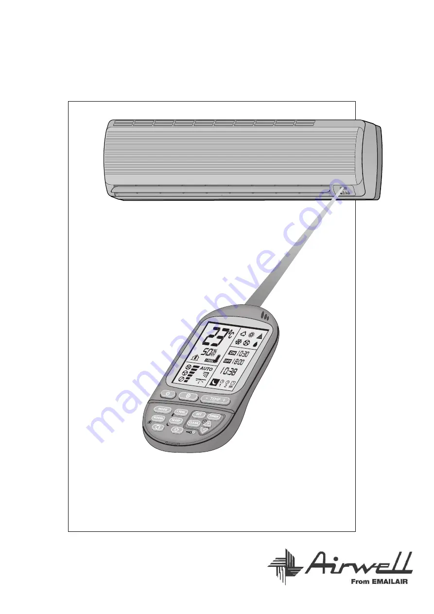
AIR CONDITIONER
SPLIT WALL-MOUNTED
PROGRAMING AND OPERATION MANUAL
XLM17RCA / GCXLM17RCA & XLM24RCA(STA) / GCXLM24RCA(STA)-S
INSTALLATION INSTRUCTIONS
Page 1: ...AIR CONDITIONER SPLIT WALL MOUNTED PROGRAMING AND OPERATION MANUAL XLM17RCA GCXLM17RCA XLM24RCA STA GCXLM24RCA STA S INSTALLATION INSTRUCTIONS...
Page 2: ...ir conditioner Ventilating operation Cooling operation Cooling operation with auto fan mode Heating operation Heating operation with auto fan mode Auto cooling heating operation Dry operation Selectin...
Page 3: ...HUIRUPHG E DQ H SHULHQFHG DLU FRQGLWLRQLQJ LQVWDOOHU REVHUYLQJ JRRG UHIULJHUDWLRQ SUDFWLFH OHFWULFDO FRQQHFWLRQV DQG SRZHU FRUG UHSODFHPHQW VKRXOG RQO EH PDGH E DXWKRUL HG HOHFWULFLDQV DQG LQ DFFRUGDQ...
Page 4: ...GHU 5HPRWH FRQWURO 2XWGRRU XQLW DLU RXWOHW 2XWGRRU XQLW DLU LQWDNH RQGHQVDWH WXEH RQWURO ZLUH 3RZHU FDEOH LTXLG OLQH 6XFWLRQ OLQH RUL RQWDO LU ORZ HIOHFWLQJ RXYHUV 8QLW V LQGLFDWRUV 3RZHU FRUG LU ILOW...
Page 5: ...e place where the remote control is located Generally the temperature sensor is located behind the intake grille of the air conditioner This function is designed to provide a personalized environment...
Page 6: ...the remote control They are capable of capturing small particles down to 0 1 microns Such as atmospheric and house hold dust coal dust insecticide dust mites pollen pet dander tobacco smoke particles...
Page 7: ...ns between the remote control and the signal receptor Do not drop or throw the remote control Do not place the remote control in a location exposed to direct sunlight or next to a heating unit and or...
Page 8: ...ZKHQ 0RGH LV SUHVVHG G 5 6 7 87721 3UHVV WR WXUQ RII WKH 7 5 LQGLFDWRU DQG WR UHVHW WKH ILOWHU IXQFWLRQ DIWHU WKH FOHDQ ILOWHU KDV EHHQ UHLQVWDOOHG 3UHVV WR FDQFHO WKH EX HU DQQRXQFHU LI HOHFWHG H 6...
Page 9: ...D and AUTO FAN button 4 I FEEL temperature sensing mode button 3 Operation mode selection button COOLING HEATING AUTO COOL HEAT DRY FAN 2 1 START STOP button Room temperature UP button 5 TIMER CLEAR b...
Page 10: ...w in order to quickly lower the room temperature It will then automatically switch to the low air flow to quietly maintain the selected temperature COOLING OPERATION Select the COOLING mode by pressin...
Page 11: ...to vertical air delivery for heating At start the air conditioner will select its mode of operation according to the room temperature and the temperature setting DRY OPERATION Select the DRY mode by p...
Page 12: ...resume operation when initiated B WEEKEND TIMER OPTIONAL The weekend timers WKT1 and WKT2 can be set for ON and OFF separately for two different time periods for two days only It will be effective on...
Page 13: ...utton Press the SET button Set the hours and minutes Press the SET button 4 3 2 1 Timer OFF is cleared 1 The ON time is activated at 10 30 the time ON icon will light 2 Time OFF icon OFF time digits w...
Page 14: ...to advance the time and press the HOUR down button retract 1 The ON time is activated at 10 30 the time ON icon will light 2 Timer OFF icon OFF time digits will blink 1 Set the OFF time at 18 30 2 Pr...
Page 15: ...le keeping the OFF time setting TO CANCEL THE ON OFF TIME SETTINGS Press CLEAR button Press TIMER button to select a timer Press SET button Press SET button 4 3 2 1 Confirm the new setting The selecte...
Page 16: ...etting follow the steps described above TURNING OFF THE AIR CONDITIONER Press START STOP button 1 to turn off the air conditioner Indicator B on the air conditioner will be turned off Indicator A will...
Page 17: ...utomatically High outdoor temperature Outdoor coil overheating Stops compressor when approaching over heating conditions Resumes operation automatically Operating indicator B blinks Heating Low outdoo...
Page 18: ...should be removed from the unit and replaced once a year as shown in figures 1 2 and 3 1 Pulling out the filter 2 Replacing and securing the filter in its frame 3 Sliding the filter back in its place...
Page 19: ...ined When restarted operation will be resumed in the last mode of operation However if the timer was used the unit will be turned off by the timer only if the remote control is aimed at the unit Other...
Page 20: ...onditioner Do not insert any objects in the air outlet of the indoor or outdoor units Do not splash water on the air conditioner 12 6 6 5 7KHUH PD EH KLVVLQJ VRXQG GXULQJ RSHUDWLRQ RU MXVW DIWHU VKXW...
Page 21: ...blow out from indoor unit De icing protection mode is activated Unit in AUTO FAN mode Over cooling in DRY Normal operation in HEATING mode Normal operation in DRY mode COOLING DRY or HEATING does not...
Page 22: ...DOOR UNITS 3 ELECTRICAL REQUIREMENTS 4 INSTALLATION OF THE INDOOR UNIT 5 CONDENSATE HOSE CONNECTION 6 ELECTRICAL CONNECTIONS BETWEEN INDOOR AND OUTDOOR UNITS 7 REFRIGERANT TUBING 8 FINAL TASKS INSTALL...
Page 23: ...ion should not disturb neighbors with noise or exhaust air 5 Place the mounting pads under the unit legs 6 Install the outdoor unit as shown Refer to the technical and service 7 When the unit is insta...
Page 24: ...Fig 3 1 To attach 2 To remove Fig 6 1 Mounting pads x4 Fig 5 Fig 6 80 mm 50 mm Fig 4 Fig 4 Direction of tubing Fig 3 Fig 3 Length of electric cable to mains 1800 950...
Page 25: ...ndoor unit 7 Replace the screws and their caps Fig 5 1 Lift front panel 2 Screw caps 3 Screw 4 Horizontal deflection levers 5 Screws 6 Front panel REFRIGERATION TUBE ROUTING 1 There are five possible...
Page 26: ...sure that the condensate drain hose is at all points in a downward slope manner 4 When installing the drain hose avoid traps and U bends The end of the drain hose should not be immersed in water 5 For...
Page 27: ...ltiple wire power cable with the cable clamps 6 Fasten the twin wire cable to the power cable with cable ties 2 5 wires x 2 5 mm For units up to 3 5kW input Twin wire cable For units up to 1 8kW input...
Page 28: ...oor and outdoor units purge the air from the tubes and indoor unit as follows 1 Connect the charging hoses with a push pin to the low and high sides of the charging set and the service port of the suc...
Page 29: ...etween hole sides and tubing with sealer 3 Attach wiring and tubing to the wall with clamps where necessary 4 Operate the air conditioner together with the customer and explain all functions 5 Explain...
Page 30: ...IDE Offices on the parkSuite 27 8 Greenhill Road Wayville SA 5034 TEL 08 8372 7866 FAX 08 8372 7816 PERTH Suite 23 350 Cambridge St Wembley WA 6014 TEL 08 9284 0800 FAX 08 9284 0600 NEWCASTLE Suite 3...