


AirVelocity 1500 Installation Guide
DUG01560
Airspan Commercial and Internal Use
25
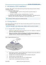
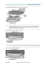
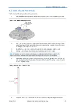
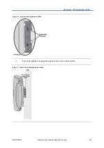
Remove the plastic cover to expose the connectors.
8.
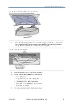
Connect the necessary cables to the relevant ports.
Connect to power
Copper Ethernet port
– ETH – if applicable
Fiber Ethernet port
– SFP – if applicable
GPS cable - to the GTPS port
– when required
Debug port
– if needed
9.
Once all connections are completed, replace cover.
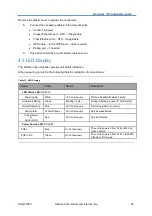
4.3 LED Display
The LEDs on the unit panel, provide unit status indication.
When powering up refer to the following table for indication of current status:
Table 13: LED Display
Name
Color
Status
Description
eNB Status LED
(OK LED)
Powering Up
White
On Continuously
Till the eNodeB SW starts loading
Software initiating
Green
Blinking (~3Hz)
During initiating
process till “All Running”
Normal Operation
Blue
On Continuously
Normal operation (no alarm)
Major Alarm
Yellow/Orange
On Continuously
Service
not
affected
Critical Alarm
or
Sector OOS
Red
On Continuously
Service affected
Power Source LED
(PS LED)
POE+
Blue
On Continuously
The unit is powered from PoE+ (802.3at)
class 4 source
POE++/DC
Green
On Continuously
The unit is powered from PoE++ (802.3bt)
Class 6 or DC source