AirSpeed 1050 B3 Installation Guide
DUG01593
Airspan Commercial and Internal Use
11
Antenna System
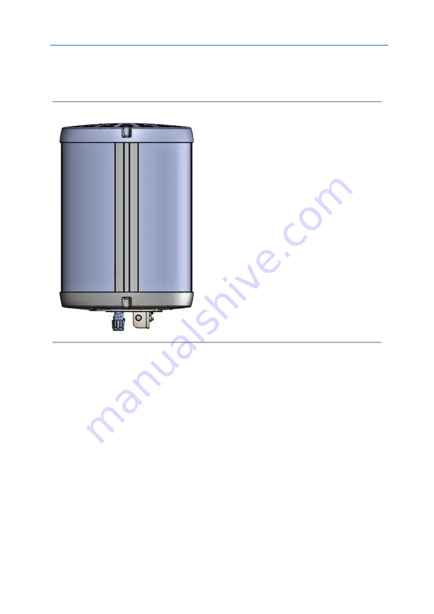
The AirSpeed 1050 B3 includes embedded antennas: 2x SBA. Each SBA includes two antenna elements which can be switch on/off.
Figure 1: AirSpeed 1050 B3
Page 1: ...AirSpeed 1050 B3 Installation Guide Part Number DUG01593 System Release 16 5 Revision A Published December 2020 ...
Page 2: ...of whatever nature in respect of these documents including without limitation the accuracy or completeness of any information facts and or opinions contained therein No responsibility is assumed by Airspan Networks Ltd for the use of the documents nor for the rights of third parties which may be effected in any way by the use thereof The provision of these documents and the documents themselves do...
Page 3: ...ications 2 General 2 Général 3 Important Safety Instructions 3 Safety 3 Securite 4 Warning of Hazardous Voltages 4 Attention aux Voltages Hasardeux 5 Adherence to European Directive 2014 53 EU 5 Warning Symbols 5 Service Information 5 UL Information 6 Lightning Protection 6 Outdoor Cabling 7 DECLARATION OF CONFORMITY 7 GPS Compliance 9 Maximum Output TX Total Power 10 Power Consumption 10 Product ...
Page 4: ...ions 18 3 2 Bottom View 19 3 3 Power 19 3 3 1 Environmental 19 3 4 LEDs Display 20 4 Installation of AirSpeed 1050 B3 21 4 1 Mounting Adaptor Assembly 22 4 2 Mounting 22 4 2 1 Securing the Unit to the Pole Mounting Arm 22 Connect and Manage Cables 24 4 3 Connecting the Ground Cable 24 4 4 TX Power Monitoring Port 24 4 5 Cable Connection 24 4 5 1 AC Cable Preparation 25 4 5 2 Fiber Ethernet SFP Cab...
Page 5: ...ting Arm example 23 Figure 9 Ground Connection 24 Figure 10 Stripping Dimensions AC Cable 25 Figure 11 Open Housing Lock 25 Figure 12 Seperate into Sections 26 Figure 13 Insert Gland Nut 26 Figure 14 Pass Cable Through 26 Figure 15 Insert Wire to Housing 27 Figure 16 AC Wire Placement 27 Figure 17 Tighten Three 3 Set Screws 27 Figure 18 Cable Click in Place 28 Figure 19 Place Split Rubber Gland 28...
Page 6: ...Cable 35 Figure 45 Insert Rubber Gland on Cable 35 Figure 46 Insert Housing onto Cable 35 Figure 47 Insert Holder onto RJ45 35 Figure 48 Holder into Housing Base 36 Figure 49 Align RJ45 into Holder 36 Figure 50 Lift Lever 36 Figure 51 Insert Gland 36 Figure 52 Tighten Gland Nut 37 Figure 53 Secure Housing Lock 37 Figure 54 Removal from the Mounting Arm 39 Tables Table 1 AirSpeed 1050 B3 FCC Maximu...
Page 7: ...AirSpeed 1050 B3 Installation Guide DUG01593 Airspan Commercial and Internal Use v Table 13 Tool Requirements Removal 38 ...
Page 8: ...duct Management YSH Product Line Manager R D EPI Digital HW Group Manager Revision History Document owner Yoav Shilo PLM Revision Date Summary of Changes Created by 0 1 0 2 June 2019 Initial document comments MSF 0 3 July 2019 Modified from comments MSF A August 2019 Publish MSF A1 August 2019 Added to recommended gland sizes MSF A2 September 2019 Added LED table AC pinout updated bracket MSF A3 D...
Page 9: ...or relocate the unit Increase separation between the units and or End Device Connect the equipment to a circuit different from that to which the power source is connected Modifications Any changes and modifications to this device that are not expressly approved by Airspan Networks may void the user s authority to operate the equipment General Only qualified personnel should be allowed to install r...
Page 10: ...ains instructions and warnings that should be followed during installation and operation Failure to follow these instructions could cause bodily injury and or product failure Safety 1 Read this guide and follow all operating and safety instructions 2 Supply cord is not shipped with the unit and is to be provided by user Installation is to be performed by a qualified electrician according to local ...
Page 11: ... non clémente 8 Utiliser uniquement chiffon de coton pour nettoyage Ne pas utiliser de produits liquides ou d aérosols Déconnecter le produit de la source d alimentation avant nettoyage 9 L unité ne doit pas être située trop près de lignes électriques ou autres circuits de puissance avec lesquels il pourrait entrer en contact 10 L émetteur radio doit être correctement relie a la terre afin de le p...
Page 12: ... and reference levels should provide a high level of protection as regards the established health effects that may result from exposure to electromagnetic fields Airspan equipment is compliant with CE and R TTE regulations and can be operated in all EU European Union locations listed below Country Code BE EL LT PT BG ES LU RO CZ FR HU SI DK HR MT SK DE IT NL FI EE CY AT SE IE LV PL UK Warning Symb...
Page 13: ...ear strike Lightning protection and grounding practices in local and national electrical codes serve to minimize equipment damage service outages and serious injury The antennas are to be DC grounded so surge protection may not be required Reasons for lightning damage are summarized as Poorly grounded tower antenna sites that can conduct high lightning strike energy into equipment Lack of properly...
Page 14: ... English This equipment is in compliance with the essential requirements and other relevant provisions of Directive 2014 53 EU Español Por medio de este Airspan declara que la unidad cumple con los requisitos esenciales y cualquier otra disposición aplicable o exigible de la Directiva 2014 53 UE Greek ΜΕ ΤΗΝ ΠΑΡΟΥΣΑ ΠΡΟΔΙΑΓΡΑΦΗ η Airspan ΔΗΛΩΝΕΤΑΙ ότι η μονάδα συμμορφώνεται με τις ουσιώδεις απαιτή...
Page 15: ... ustreznimi določbami Direktive 2014 53 EU Slovak Airspan týmto vyhlasuje že tento prístroj spĺňa základné požiadavky a všetky príslušné ustanovenia Smernice 2014 53 EÚ Suomalainen Airspan vakuuttaa täten että laitteen tyyppi on direktiivin 2014 53 EU olennaisten vaatimusten ja muiden asiaankuuluvien säännösten mukainen Swedish Därmed intygar Airspan att denna enhet överensstämmer med de väsentlig...
Page 16: ... 22 Class B EN 50081 1 Generic Emissions Class B EN 50082 1 Generic Immunity Class B EN 61000 4 2 Electrostatic Discharge Immunity EN 61000 4 3 Radiated RF EM Field Immunity Test EN 61000 4 4 Electrical Fast Transient Burst Test EN 61000 4 6 Conducted Immunity EN 61000 4 8 Magnetic Field Immunity Note A GPS is recommended for synchronizing the unit included in the system Note An optional GPS Light...
Page 17: ...tion Do not set maximum output TX power to higher than local regulations Power Consumption AirSpeed 1050 B3 power consumption is described in the following table Table 2 Power Consumption Duplex Tx Power at RF Port dBm Nominal Power Consumption W Max Power Consumption W FDD 4x 32 60 90 FDD 4x 34 75 105 Product Variants Table 3 Variants Product Name Product Code Description AirSpeed 1050 B3 M1 Fibe...
Page 18: ...llation Guide DUG01593 Airspan Commercial and Internal Use 11 Antenna System The AirSpeed 1050 B3 includes embedded antennas 2x SBA Each SBA includes two antenna elements which can be switch on off Figure 1 AirSpeed 1050 B3 ...
Page 19: ...e procedures include Verify prerequisites Install the AirSpeed 1050 B3 Connect and manage cables Intended Audience This guide is intended for persons who are responsible for installing the AirSpeed 1050 B3 equipment These persons should have a working knowledge of the equipment Related Reading The following documents contain related information AirSpeed 1050 B3 Product Datasheet Airspan LTE Commis...
Page 20: ...ends an issue number for your reference The system uses this issue number to categorize and store e mails under the appropriate issue To help Customer Care Help Desk identify your issue include the issue number and your Customer Care Helpdesk account details in all further communications Main Operations Airspan Communications Ltd Capital Point 33 Bath Road Slough Berkshire SL1 3UF United Kingdom T...
Page 21: ...dsets indoor UEs outdoor UEs and USB dongles from several ODMs using various chipsets For an updated of interoperability list please contact your nearest Airspan Sales Representative Note For management please refer to the Airspan LTE Commissioning Manual as well as the Netspan User Manual 1 1 1 Deployment AirSpeed 1050 B3 perfectly fits the requirements of the hard zoning outdoor locations such a...
Page 22: ...AirSpeed 1050 B3 Installation Guide DUG01593 Airspan Commercial and Internal Use 15 Figure 2 AirSpeed 1050 B3 Note The illustration above displays the AirSpeed 1050 B3 unit with mounting adaptor ...
Page 23: ...ghten to a torque of no more than 15 Nm 11 ft lb max Knife For cable preparation Small side cutters For power cable preparation Wire strippers For power cable preparation 2 2 Verify the Parts and Kits Note Verify order and requirements to ensure the correct unit type is being installed Note Currently available AS105 U03M1 B08A Table 5 AirSpeed 1050 B3 Components Installation Kit Part Product Code ...
Page 24: ...ernal Use 17 Installation Kit Part Product Code AS P N Description Connector Adapter SFP CON ADP OCT SFP 1 10135746 OCTIS Connector Adapter SFP ordered separately Connector Adapter RJ45 CON ADP OCT RJ45 1 300 20 062 ETH RJ45 connector Right R pitch 26mm ordered separately ...
Page 25: ...peed 1050 B3 Overall Dimensions 3 1 AirSpeed 1050 B3 Physical Dimensions Table 6 AirSpeed 1050 B3 Physical Dimensions Dimensions H x Ø Comment Dimensions 373x 260 mm 14 7 x 10 2 The physical dimensions exclude connectors and mounting adaptor Weight 12 3Kg 29 9Lbs Weight of mounting adaptor is 1 5 Kg in addition to the unit weight Table 7 AirSpeed 1050 B3 Material Color Material Color ASA main rado...
Page 26: ...nnection to AC power source Operational Voltage Range AC 90 240 VAC 50 60Hz 3 3 1 Environmental Note AirSpeed 1050 B3 is not meant to be used in a Marine environment AirSpeed 1050 B3 meets the following environmental requirements GR 63 Storage and Transportation ETSI EN 300 019 1 4 Operational non weather protected equipment ETSI EN 300 019 1 1 Storage weather protected not temperature controlled ...
Page 27: ...LEDs Display Two 2 LEDs appear on the bottom of the unit providing unit status indication When powering up refer to the following table for indication of current status Table 9 LED Display Name Color Status Description Powering Up Orange On Continuously Till the eNodeB SW starts loading Software loading Green Blinking 3Hz While SW is loading Normal Operation Green On Continuously Normal operation ...
Page 28: ... Recommended When installing the unit care should be taken so that the unit should be distanced from any obstructions above that can interfere with clear sky conditions needed for good GPS reception It is recommended to install the unit in a location which enable GPS reception from at least four satellites can be tested with general mobile application In the event this is unavoidable there is the ...
Page 29: ...to a torque of no more than 5 2 Nm 46 02 in lbs max 4 2 Mounting The following images show the assembly of the AirSpeed 1050 B3 onto the pole mounting arm not supplied responsibility of the installer Note The following pictures are for illustration purposes only 4 2 1 Securing the Unit to the Pole Mounting Arm To mount the AirSpeed unit to the pole mounting arm not supplied perform the following 1...
Page 30: ...n both sides 5 Gradually tighten the four 4 bolts to fix the AirSpeed 1050 in place tightened to a torque of no more than 15 Nm 11 ft lb max M8 bolt Work in an alternating pattern this will ensure that the stress is applied evenly as the bolts are tightened Note Using higher than specified tightening torque might damage the unit or mounting arm Note Use an appropriate wrench only and tighten with ...
Page 31: ...Monitoring Port There is the option to monitor TX power via the available monitoring ports SMA Jack B H found on the bottom of the AirSpeed 1050 B3 unit See Figure 4 AirSpeed 1050 B3 Bottom 4 5 Cable Connection The following explains the general instructions on how to connect a power cable AC and the SFP Copper Ethernet cables to the AirSpeed 1050 B3 unit Danger Hazardous voltage Before working en...
Page 32: ...y rated and easily accessible circuit breaker shall be incorporated externally to the equipment Power source disconnection is required before disconnecting the power connector Warning This unit incorporates double pole neutral fusing Both the Line Neutral have fuses in them Warning The onsite source circuit breaker 6A should be gang operated two 2 pole single phase type Note Required AC power cabl...
Page 33: ...perate into Sections 4 Insert the Gland nut through the other end of the cable Figure 13 Insert Gland Nut 5 Feed the end of the source power cable through the housing of the AC connector Figure 14 Pass Cable Through 6 Insert the prepared ends of the cable into the inner part of the connector housing Caution Verify the wire polarity before securing ...
Page 34: ...ing 7 Verify the wires are in their correct stations Figure 16 AC Wire Placement Table 11 Wire Pinout Connection Position Ground 1 Line 4 Neutral 3 8 Tighten the three 3 set screws as shown below Figure 17 Tighten Three 3 Set Screws 9 Insert into outer housing until click in place align marks for proper alignment ...
Page 35: ...below Table 12 Recommended Gland Sizes Cable Diameter Recommended Gland Size From 6 6mm Min to 7 95mm Max Φ8 From 7 6mm Min to 8 95mm Max Φ9 From 8 6mm Min to 9 95mm Max Φ10 Note The gland size is written on the edge of the gland Figure 20 Gland Size on Edge Note The tolerances of the diameter should be taken into account to make sure it is always within the specified range 12 Place the tightening...
Page 36: ...mm wrench Caution Do not over tighten the Gland nut The Gland nut should be tightened to a torque of no more than 2 5 3 0 Nm 1 84 2 21 ft lb max Figure 22 Tighten Gland Nut 14 After tightening the gland nut close the lever Figure 23 Close the Lever 15 Secure the lock by sliding the secondary lock button into the locked position Figure 24 Secure Lock 16 Secure the lever with the Metal Plastic tie t...
Page 37: ...o tension on the connector so that it is easy to disconnect and re connect for future maintenance actions 4 5 2 Fiber Ethernet SFP Cable Preparation Note Additional parts required for the SFP assembly LC Duplex cable assembly SFP Transceiver The following displays the proper steps for SFP cable preparation 1 Have the pre assembled LC Duplex cable assembly ready Figure 26 Stripping Dimensions SFP C...
Page 38: ... nut through the front end of LC Duplex assembly Figure 29 Gland Nut on Cable 4 Insert the split tightening cone from the side of the cable Figure 30 Insert Tightening Cone on Cable 5 Insert the split rubber gland from side of the cable For recommended gland size see Table 12 Recommended Gland Size Figure 31 Insert Rubber Gland on Cable 6 Pass the LC Duplex cable thru the housing ...
Page 39: ...ransceiver A click is heard when engaged Figure 33 Insert Cable into Transceiver 8 Insert the holder subset section from the front end of Transceiver Figure 34 Insert Holder over theTransceiver 9 Fix the holder into the housing base A click is heard when engaged Figure 35 Holder into Housing Base 10 Secure the holder into the transceiver click when engaged ...
Page 40: ...base slightly so that the rubber gland tightening cone and gland nut can be inserted and tightened correctly Figure 37 Lift Lever 12 Push to insert the rubber gland Figure 38 Insert Gland 13 Push to insert the tightening cone Figure 39 Insert Cone 14 Tighten the gland nut with a 21mm wrench to a torque of no more than 2 2 5 Nm 1 47 1 84 ft lb max ...
Page 41: ... Ethernet Cable Preparation Note A pre assembled RJ45 cable is required for the Copper Ethernet assembly The following displays the proper steps for the Copper ETH cable preparation 1 Have the pre assembled RJ45 cable assembly ready Note Diameter of cable is in the 6 to 7mm 0 24 0 28 range Figure 42 Pre assembled RJ45 Cable 2 Insert the gland nut through the front end of RJ45 assembly Figure 43 Gl...
Page 42: ...the split rubber gland from side of the cable Note Inner diameter of rubber gland is in the range of 7 to 8mm 0 28 0 31 range Figure 45 Insert Rubber Gland on Cable 5 Insert the housing onto the RJ45 cable Figure 46 Insert Housing onto Cable 6 Insert the holder section onto the front of the RJ45 Figure 47 Insert Holder onto RJ45 7 Fix the holder into the housing base A click is heard when engaged ...
Page 43: ...g cap to ensure proper location then lock the cap Figure 49 Align RJ45 into Holder 9 Lift the lever of housing base slightly so that the rubber gland tightening cone and gland nut can be inserted and tightened correctly Figure 50 Lift Lever 10 Push the rubber gland to insert in place then push the tightening cone to insert in place Figure 51 Insert Gland 11 Tighten the gland nut with a 21mm wrench...
Page 44: ...593 Airspan Commercial and Internal Use 37 Figure 52 Tighten Gland Nut 12 Close the lever and secure the lock by sliding the secondary lock button so that lever can t be lifted assembly is now ready for insertion Figure 53 Secure Housing Lock ...
Page 45: ...ich is holding the locking lever mechanism closed 2 Grasp the sides of the AC cable connector housing and slide the secondary lock up to disengage it 3 Lift up the locking lever to open 4 Gently remove the AC cable housing from the Power port of the AirSpeed unit 5 3 Fiber Ethernet SFP Cable Disconnection 1 Grasp the sides of the SFP Transceiver housing and slide the secondary lock up 2 Lift up th...
Page 46: ...Arm To remove the AirSpeed unit from the pole mounting arm perform the following 1 Loosen then remove the two 2 M8 Hexhead bolts from the threaded holes on the lower portion of mounting arm 2 Loosen the two 2 upper bolts on the mounting adaptor s upper slots 3 Lift up the unit and slide off of the mounting adaptor loosened bolts Figure 54 Removal from the Mounting Arm 4 After removal of the unit r...
Page 47: ... pole power pole o Method of reaching desired positions ladders Elevated work platform o Main fuse block available where needed o Configuration programming details known o All equipment items available at the installation site o AirSpeed 1050 B3 unit mounting adaptor Tools For further information see Verify the Tools o Appropriate wrench s for unit assembly o Knife o pliers o Small side cutters o ...
Page 48: ...ackhaul DC Direct Current eNb eNodeB ETH Ethernet cable FDD Frequency Division Duplex FTP File Transfer Protocol LTE Long Term Evolution marketed as 4G LTE is a standard for wireless communication of high speed data for mobile phones and data terminals NEC National Electric Code UE User Equipment WEEE Waste Electrical and Electronic Equipment ...