Service Instructions
Syntron
®
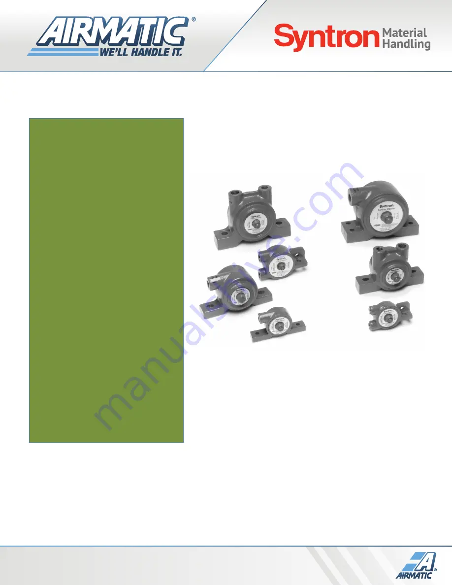
Pneumatic Turbine Vibrators Model: TAM
,
TB
TBM
AIRMATIC INC
airmatic.com
|
215.333.5600
[email protected]
Page 1: ...Service Instructions Syntron Pneumatic Turbine Vibrators Model TAM TB TBM AIRMATIC INC airmatic com 215 333 5600 infocenter airmatic com...
Page 2: ...1 Syntron Pneumatic Turbine Vibrators Models TAM TB and TBM Installation Operation Maintenance...
Page 3: ...troduction 3 Selecting the proper Bin Vibrator 4 Installation Check List 5 Installation 6 Chutes 11 Operation 11 Plumbing the Vibrator 12 Maintenance 13 Recommended Spare Parts 13 TAM Series Specifica...
Page 4: ...rawings may be attached to this manual The information contained therein takes precedence over corresponding information printed in this manual INTRODUCTION Syntron Pneumatic Turbine Vibrators are air...
Page 5: ...ds of the material in the sloping part of the bin only Normally this is the only place where friction between the material and the bin wall must be broken For conical bins calculate as follows 261 x D...
Page 6: ...tor plus the maximum material in the chute See page 11 for more details INSTALLATION CHECKLIST CAUTION The warranty is void if vibrators are not properly installed During installation follow and check...
Page 7: ...ount it diametrically opposite to the first vibrator For coarse materials mount one vibrator one third of the way up the side of the bin and the other vibrator halfway up For fine materials mount the...
Page 8: ...3 in 5 to 8 in 3in TB 100 130 160 6 to 8 5 mm 127 to 203 mm 76 mm TBM 100 130 190 TBM 250 3 8 in 6 to 8 in 3in TB 250 9 5 mm 150 to 203 mm 76 mm TBM 320 380 440 510 570 1 2 to 5 8 in 12 to 24 in 4in...
Page 9: ...mm welds with 3 inch 76 mm spaces between the welds Refer to Figure 2 POSITION OF THE CHANNEL AND MOUNTING PLATE FIGURE 2 If the bin plate is 3 16 inches or less 4 8 mm weld the mounting plate to the...
Page 10: ...er the first 10 to 15 minutes of operation retighten the bolts Continue to check them periodically for tightness CAUTION A loose vibrator can cause damage to the bin and the vibrator WARNING Install a...
Page 11: ...10 VARIOUS VIBRATOR INSTALLATIONS cont d...
Page 12: ...books or easily measured by dumping a cup of material on a table The angle the material makes between the table and the cone is the angle of repose OPERATION CAUTION Do not operate the vibrator while...
Page 13: ...frequency of the vibrator By throttling the flow the desired material discharge rate can be found and the natural frequency of the bin or hopper can be avoided Avoid speeds frequency at which the bin...
Page 14: ...heck the mounting hardware to ensure that it is tight Also make sure that the maximum operating temperature 180 F 82 C and the maximum air pressure 60 or 80 psi 4 2 or 5 6 kgf cm2 are not exceeded Ref...
Page 15: ...n changes Decibel from A scale at 1 meter and 80 psi N Centrifugal force in Newton Rule of thumb for sizing 1 Ib Vibrator Force for each 10 Ib of Bin Content at 80 psi or 9 8 N Vibrator Force for each...
Page 16: ...15 TAM SERIES...
Page 17: ...80 psi N Centrifugal force in Newton Rule of thumb for sizing 1 Ib Vibrator Force for each 10 Ib of Bin Content at 80 psi or 9 8 N Vibrator Force for each 10 kg of Bin Content at 80 psi Aluminum Const...
Page 18: ...17 TBM SERIES...
Page 19: ...r and 80 psi N Centrifugal force in Newton Rule of thumb for sizing 1 Ib Vibrator Force for each 10 Ib of Bin Content at 80 psi or 9 8 N Vibrator Force for each 10 kg of Bin Content at 80 psi Aluminum...
Page 20: ...19 TB SERIES TB except Models 2000 5000 TB Models 2000 5000 AIRMATIC INC airmatic com 215 333 5600 infocenter airmatic com...
Page 21: ...metals power generation and waste water treatment applications The SERVICE GROUP provides fabrication installation and maintenance services to improve bulk materials handling efficiency mechanical cle...