


6
kg
53
85
108
156,5
kg
82
-
190,8
257,2
RAL
-
-
9010
9010
RAL
9010
9010
7024
7024
mm
2.
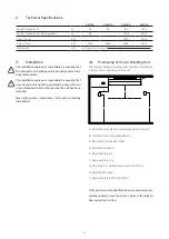
Technical Specifications
AM 150
AM 300
AM 500
AM 800
Weight, Standard unit
Weight, Standard unit + Cooling module
Colour, Panel
Colour, Case
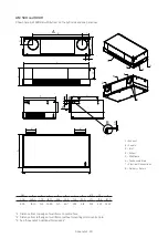
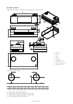
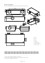
Dimensions
See “Dimensional Drawings”
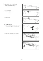
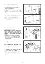
3.
Installation
The installation engineer is responsible for ensuring that
the Airmaster air handling unit is properly secured in a
horizontal position.
The installation engineer is responsible for ensuring that
any existing functions in the wall/ceiling (e.g. vapour barrier)
are restored and fully functional once the unit has been
installed.
Read this section “Installation” fully before starting
installation!
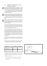
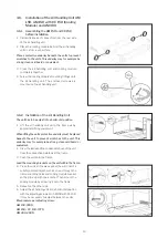
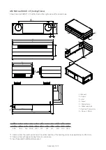
3.1.
Positioning of the Air Handling Unit
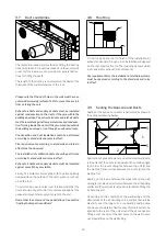
The diagram below shows the most important dimensions
relating to the positioning of the unit.
B
A
C
E
F
D
J
H
G
A: Extraction (may also be on the right side of the unit)
B: Distance from ceiling: Max. 50 mm
C: Min. distance from wall: 0.5 m
D: External CO
2
sensor
E: Approximately 1 m
F: Approximately 2 m
G: Free space for maintenance work min. 0.95 m
H: External PIR sensor
J: Approximately 2,25 m (1,8-2,5 m)
A CO
2
sensor must not be fitted close to a window or door.
A smoke detector must not be too close to the inlet air
flow and extract air flow.