background image

Manual V1.00_2009_V5 


6. Flight 

recording 

menus


6.1 Menus-displays overview: 

 
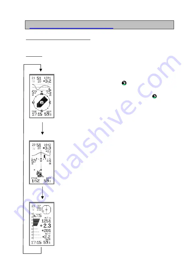
The flight mode contains 3 screens. 

 
NOTE: 

The following screenshots are examples from flight and do not match the screen 

at launch. 
 

BaroCompass Display  

(Ill. 1)


(Details 8.4) 


The default screen to appear when a new flight is initiated is the 
BaroCompass screen. Press the Key3 

 briefly to toggle between the 

BaroCompass, the Thermal and the Vario screens. When the 
instrument is set to manual in Settings, these three screens are 
displayed one after the other for each short click on Key3 

. In Auto 

mode (recognised by the small A in the centre right) the instrument 
automatically switches between BaroCompass and Thermal mode, 
when climbing to Thermal, when gliding to BaroCompass. Toggle to 
Vario to void the auto setting. 


Thermal Display 

(Ill. 2)


(Details 8.6)


In this screen the thermals are visualised as clouds of pixels on the 
screen. After some thermalling the shape of the thermal should 
become apparent. The display is wind-drift compensated. After 1 full 
circle the wind distribution curve appears on the screen. 


VARIO Display 

(Ill. 3)


(Details 8.7)


Main information in Vario display. 
Large glide angle display 
Analog Vario, Digital Vario, Average Vario 
Altitude, Alt0 


Page 

16 

Summary of Contents for XC-trainer Series

Page 1: ...Manual V1 00_2009_V5 Page 1...

Page 2: ...Manual V1 00_2009_V5 Page 2...

Page 3: ...formation contained in this manual has been gathered with attention to detail and care It is not however intended as a comprehensive product characteristics description and AIRCOTEC is only liable to...

Page 4: ...e the XC Trainer is mounted so that it does not impede the pilot s movements in the air on when launching landing Finally it is important to check that neither instrument nor part thereof may come loo...

Page 5: ...sure that water does not penetrate the instrument cover It is NOT waterproof and particularly salt water may lead to extensive damage to the electronics Protect from salt water spray rain and humidity...

Page 6: ...or XC TrainerEasy Instrument in Set XC trainerEasy_BH or XC trainerEasy_GZH or XC trainerEasy_DH XC trainerEasy _BH or XC trainerEasy _GZH or XC trainerEasy _DH Instrument Quick charger fort he batter...

Page 7: ...irmware 2 1 Firmware Version V1 00 12 2 2 Flight Recorder 12 2 3 Waypoints and routes 12 2 4 Available data in the display 12 2 4 1 Permanent displays 12 2 4 2 Additional information in the BaroKompas...

Page 8: ...search 18 8 1 2 Auto Start flight recording 18 8 2 Manual Start 19 8 2 1 Manual start 19 8 2 2 Manual altitude setting 19 8 3 Ordinary flight recording 20 8 4 BaroCompass Mode 21 8 5 Thermal Mode Wind...

Page 9: ...Factory Set 29 15 Vario Settings 15 1 Sinkacoustic ON OFF 30 15 2 Sink tone threshold 30 15 3 Sink tone modulation 30 15 4 Sink tone inversion 30 15 5 Vario sensitivity 30 15 6 Volume 30 15 7 Vario Nu...

Page 10: ...er Technical Specifications 1 0 Technical description XC Trainer Key Key1 Key2 Key3 Loudspeaker Identification plate with Serial number XCT Fixation Charger connection Speedboard USB and Speed sensor...

Page 11: ...tigrade from 25 to 75 degrees resolution 0 1 degrees 1 5 GPS receiver 20 channel parallel 2D 3D position WGS84 Altitude speed direction Internal aerial 1 6 Data transfer protocols XCTrainerEasy USB co...

Page 12: ...e and elapsed time since launch 2 4 2 Additional information in the BaroCompass mode Flight direction in Track UP distance and bearing to next waypoint or to a MARK Glide angle from the last 5 10 or 3...

Page 13: ...your XC Trainer Charging is completed when the red light is extinguished For your on the road needs we also provide a car charger parts number XC CAR charger 3 2 Auto Off The instrument will turn its...

Page 14: ...oint In Thermal Display Zoom 1 and 2km In Vario Display adjust sound volume In Menu Up Backwards In Start Menu MENU In main menu In Flight mode Toggle mode screens In Menu select switch to other displ...

Page 15: ...S Serial Altitude Number GPS Altitude Batterie Temperature Status only for XCT Easy INFO Automatic switch OFF Bar decreases in size from right to left if no keys are activated the instrument Key3 shut...

Page 16: ...the other for each short click on Key3 In Auto mode recognised by the small A in the centre right the instrument automatically switches between BaroCompass and Thermal mode when climbing to Thermal wh...

Page 17: ...oCompass display and Thermal display 7 4 Altitude null in VARIO display screen 3 A short click on Key1 in VARIO mode nulls the Altitude When launching this value is always set to 0 7 5 Setting the vol...

Page 18: ...ce 3D is available the bottom display reads OFF MENU The flight recording may be initiated as soon as the display reads OFF MENU 8 1 2 Beginning the flight 10 km h or 1 1m s The recording starts when...

Page 19: ...ent has acquired a position fix 8 2 2 Setting the altitude manually If the launch altitude is known it may be entered manually in MENU ALTI SET Use Key1 to decrease Key2 to increase and Key3 to confir...

Page 20: ...The follo low mean loud Details 7 5 on heading peed distribution curve with wind dicator and SOG bar Details 8 5 attery indicator in Flight mode reen ry indicator w orresponds to 3 4V and app nutes o...

Page 21: ...and Ba a screens Compass flight dire Arrow pointing to launch or to the sele direction oriented ymbols S Airplane Points back to launch large arrow pointing North N 1 2 or 3 Marks from 1 3 ma remain s...

Page 22: ...urve The wind curve is really a speed distribution curve It gives the average ground speed to be expected when gliding in any direction Two thin lines intersecting the curve indicate Upwind Downwind T...

Page 23: ...compensated see 8 6 2 Distance to selected waypoint Mark or back to launch Flight duration in hours and minutes Flashing bearing to next waypoint in this case almost due west TAS True Airspeed Only w...

Page 24: ...om 5 9m s the bar decreases in size from behind Clock with hours and minutes ALT in m or ft Altimeter Vario averager may be set to 10 20 or 30sec ALT 0 in m or ft Auto nulls at launch may be nulled in...

Page 25: ...1 Select with Key1 or KEY2 confirm with Key3 Settings menu Landing search Store land ng i Details 11 1 Details 11 2 Emergency position Log book Send flight to PC Details 17 0 Details 12 1 Details 12 2...

Page 26: ...ates and emergency number SETTINGS Menu Description Factory setting BACK Back to main menu VARIO Vario sub Menu UTC HH MM Local time or UTC time UTC UNITS m km Units m ft km nm m km CONTRAST 8 Screen...

Page 27: ...owever not influenced by this 11 Landings 11 1 LANDING search 1 3 3 landings may be entered before the launch Select LANDING 1 3 to see the Menu In the top 1 3 of the display the new coordinates will...

Page 28: ...d time Duration max climb max Sink max altitude max speed SOG 12 2 Delete or send flight Once a flight is selected the following options become available at the bottom of the screen DEL SEND EXIT DEL...

Page 29: ...ent setting The internal clock and the data storage is always on UTC If the GPS time is not actualised the display shows UTC xx xx Changes to local time gives LOCAL xx xx 14 3 Units UNIT m Km SETTINGS...

Page 30: ...SINK TONE N all Sink tones off 15 2 Sink tone threshold SINK 1 0m s Use this function to set the sink tone threshold from 0 0 5 0m sec When set to 5 0m s the Sinktone is off as from 5 m sec the sink a...

Page 31: ...to 0 00 Back to INIT Menu INFO This display is often used to demonstrate the sensitivity of the instruments baro sensor 15 8 Sound setting SOUND 5 Use this setting to adjust the sound pitch Adjustabl...

Page 32: ...Coordinates In case of an emergency or simply for information the instrument has the option to display coordinates to be passed on via telephone The same screen displays the joint European emergency...

Page 33: ...ed PC with USB port When using the USB cable XC TrainerEasy or the Speedboard USB cable XC TrainerEasy please install the enclosed driver from the CD you may also find the driver under www aircotec co...

Page 34: ...otec TN Complete Use the menu General Interface to enter the COM port allocated to the transfer by your operating system Find the Com Port for your cable Serial RS232 USB Speedboard USB as follows Rig...

Page 35: ...opup window The actual COM port may be found under USB control units laptops The serial RS232 cable is generally allocated the COM 1 Try to disconnect then reconnect the USB cable to see how a new con...

Page 36: ...e Now the only thing missing is the nine digit software license number enter this number 17 4 Step 4 transferring a flight to TN Complete Start the XC Trainer Go to MENU FLIGHTS and select the flight...

Page 37: ...ete Press SEND the transfer protocol appears To transfer to TN Complete select TNC 1s 57K The format 9 6 K will also work albeit slower For other software select the MXP Protocol In TN Complete go to...

Page 38: ...ress on the lower screen line Enter a name for the flight data for ex XCT FLIGHT Confirm with OK TN Complete stores in the folder of your choice and adds the following data to the flight name 092905_0...

Page 39: ...flight is loaded into TN Complete and displayed The exact descriptions of the many functions may be found in the software manual accessible under Menu Open Manual or by pressing F1 The flight may also...

Page 40: ...ss fixation XC Etui XC instrument bag TN Complete license XC Speed USB USB cable via Speedboard XC SS DGH K XC SS DGH L Speed sensor with attachment for hang and paraglider with short cable K 50cm or...

Page 41: ...Manual V1 00_2009_V5 Page 41 Aircotec flight instruments GmbH Alteggerstr 8 A 8083 St Stefan i R AUSTRIA Aircotec GmbH Postfach 56 CH 6048 Horw Schweiz www aircotec com flight instruments...

Reviews: