9
System Status and Error Messages
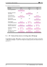
AT-1 features comprehensive self-test and diagnosis functions. These functions help the
installer and the user to identify issues and to check the system status.
In addition to transmitting failure and status messages over its data ports to connected
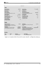
aviation instruments, AT-1 features three multi-color status LED and shows its status on the
AT-1 configuration webpage via WiFi.
For details on failures and abnormal operation, please consult the AT-1 Pilot’s Manual [1].
For a comprehensive list of possible failure modes and corresponding error messages,
please consult the AIR Avionics Error Message index [
?
]
9.1 Status LED
9.1.1 LED Positions
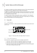
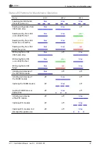
The device status of the AT-1 is shown using three multi-color LEDs located in the back of
the AT-1 unit.
Status LED 3
Status LED 1
Status LED 2
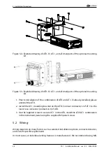
Figure 9.1.: Three status LEDs on the back of the AT-1 main unit
9.1.2 Status LED Assignment
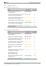
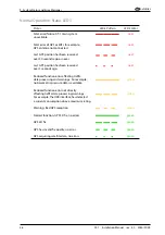
Each status LED is assigned to specific functional modules inside the AT-1:
1. Status LED 1 shows the status of the integrated 1090 MHz receiver module.
2. Status LED 2 shows the status of the integrated FLARM transceiver module.
3. Status LED 3 shows the status of the integrated GPS receiver module, the integrated
WiFi module and the general system state.
44
AT-1
·
Installation Manual
·
rev. 4.0
·
2020/01/09

