background image

25

Chapter 2 Hardware Installation

SB151-LB User's Manual

2�9 Removing and Installing a PCIe Card

Turn off your Storage Server Barebone and disconnect all peripheral 

cables and all telecommunication lines connected to riser connectors or 

ports on the riser card of the system.

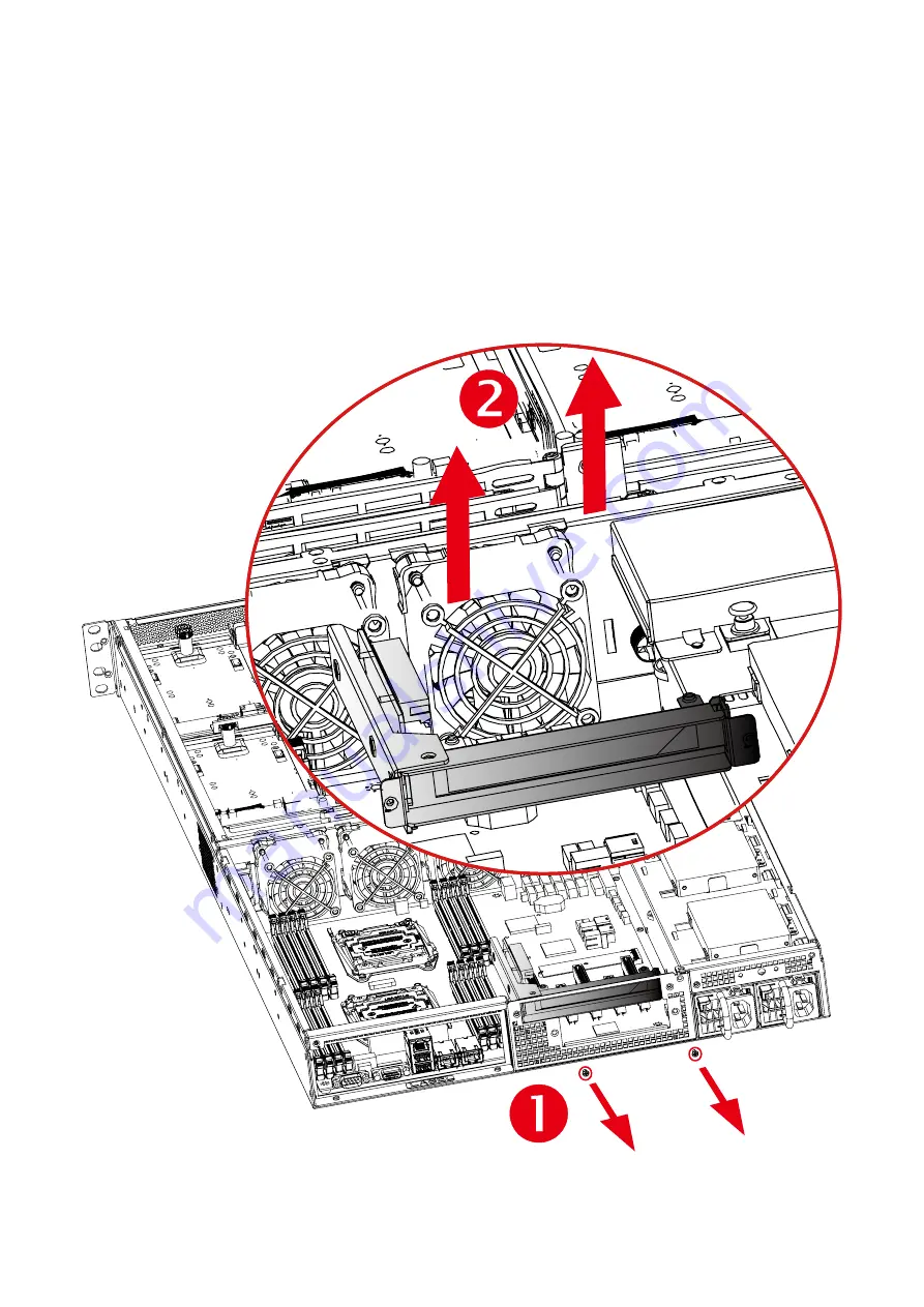
2.9.1 Removing a PCIe  Card (Slot 6)

•   Loosen the two captive screws securing the riser card to the chassis.

•  lift the riser card.

Summary of Contents for SB151-LB

Page 1: ...UM_SB151 LB_v3 1_120716 SB151 LB Storage Server Barebone User s Manual ...

Page 2: ... Fan Module 21 2 7 Removing and Installing the HDD backplane Module 23 2 8 Removing and Installing a 2 5 inch SSD 24 2 9 Removing and Installing a PCIe Card 25 2 10 Configure the SAS Signal Link setting 29 2 11 Removing and Installing a RJ45 Module 30 2 12 Tool less Blade Slide Installation Introduction 33 Chapter 3 Motherboard Settings 37 3 1 Motherboard block diagram 37 3 2 Motherboard block dia...

Page 3: ...etup 57 5 2 Method 2 Use a Dos tool Syscheck 60 5 3 Connect to BMC 62 5 4 Web UI 63 5 5 Updating BMC Firmware 70 Chapter 6 Hardware Introduction 71 6 1 HARDWARE DESIGN SPECIFICATION 71 6 2 Drive Slot Map 73 Chapter 7 Technical Support 74 ...

Page 4: ...Copyright 2016 AIC Inc All Rights Reserved This document contains proprietary information about AIC products and is not to be disclosed or used except in accordance with applicable agreements ...

Page 5: ...ception It is essential that only the supplied power cord be used 2 Use only shielded cables to connect I O devices to this equipment 3 You are cautioned that changes or modifications not expressly approved by the party responsible for compliance could void your authority to operate the equipment Disclaimer AIC shall not be liable for technical or editorial errors or omissions contained herein The...

Page 6: ...m unit chassis for a few seconds This will help to discharge any static electricity on your body Place this equipment on a stable surface when install A drop or fall could cause injury Please keep this equipment away from humidity Carefully mount the equipment into the rack in such manner that it won t be hazardous due to uneven mechanical loading This equipment is to be installed for operation in...

Page 7: ...uipment 3 The equipment has been exposed to moisture 4 The equipment does not work well or will not work according to its user manual 5 The equipment has been dropped and or damaged 6 The equipment has obvious signs of breakage 7 Please disconnect this equipment from the AC outlet before cleaning Do not use liquid or detergent for cleaning The use of a moisture sheet or cloth is recommended for cl...

Page 8: ...the contents of the carton are damaged If any damage is found do not remove the components contact the dealer where the subsystem was purchased for further instructions Before continuing first unpack the subsystem and verify that the contents of the shipping carton are all there and in good condition Enclosure Power supply fan 16 x 3 5 HDD tray included Power cord Screws kit x 1pcs Include console...

Page 9: ...2 SB151 LB User s Manual Chapter 1 Product Introduction 1 2 Specifications ...

Page 10: ... drives 1 3 General Information SB151 LB is a 1 5U rackmount chassis with 16 x 3 5 HDD hot swap Bays at Top and single 12G expander on HDD Backplane which is a high performance server storage product Front Panel System Reset button LAN1 Power LED LAN2 Power LED System HDD Activity LED Power System LED Power On Off Button ...

Page 11: ...4 SB151 LB User s Manual Chapter 1 Product Introduction Rear Panel 2 x8 PCIe 3 0 slots 750W 1 1 redundant PSU 80 Gold ...

Page 12: ...troduction SB151 LB User s Manual Major Components 750W 1 1 redundant PSU 80 Gold 4 x 6038 PWM easy swap fans 4 x 6038 PWM easy swap fans Two drawers each supports 8 x 3 5 drives AIC Server Board Libra AIC Server Board Libra ...

Page 13: ... screw 1 and loosen it by giving it two rotations and stop see letter A IMPORTANT Do not fully loosen Proceed to screw 2 and loosen it by giving it two rotations and stop see letter B Similarly loosen screws 3 and 4 Repeat steps A and B by giving each screw two rotations each time until all screws are loosened Lift the heatsink straight up see letter C R E M O V E R E M O V E L G A 2 0 1 1 3 S U P...

Page 14: ...r by doing the following 1 Touch the metal chassis before touching the processor or server board Keep part of your body in contact with the metal chassis to dissipate the static charge while handling the processor 2 Avoid moving around unnecessarily R E M O V E R E M O V E L G A 2 0 1 1 3 S U P P L I E R I D E N T I F I C A T I O N H E R E I N S T A L L P R O C E S S O R B E F O R E R E M O V I N ...

Page 15: ... Plate see letter A While holding down the lever handle with your other hand lift open the Load Plate see letter B B REMOVE R EM O V E L G A 2 0 1 1 3 S U P P L I E R I D E N T I F I C A T I O N H E R E I N S T A L L P R O C E S S O R B E F O R E R E M O V I N G C O V E R S A V E A N D R E P L A C E C O V E R I F P R O C E S S O R I S R E M O V E D A ...

Page 16: ...e letter C Carefully place Do NOT drop the CPU into the socket CAUTION The pins inside the CPU socket are extremely sensitive Other than the CPU no object should make contact with the pins inside the CPU socket A damaged CPU socket pin may render the socket inoperable and will produce erroneous CPU or other system errors if used NOTE The underside of the processor has components that may damage th...

Page 17: ... down on the locking lever on the CLOSE 1st side see letter A Slide the tip of the lever under the notch in the load plate see letter B Make sure the load plate tab engages under the socket lever when fully closed b Repeat the steps to latch the locking lever on the other side see letter C Latch the levers in the order as shown NOTE The socket cover should be saved and re used should the processor...

Page 18: ...s screwdriver start with screw 1 and engage screw threads by giving it two rotations and stop see letter C Do not fully tighten Proceed to screw 2 and engage screw threads by giving it two rotations and stop see letter D Similarly engage screws 3 and 4 Repeat steps C and D by giving each screw two rotations each time until each screw is lightly tightened up to a maximum of 8 inch lbs torque see le...

Page 19: ...2 1 4 Removing the Processor NOTE Remove the processor by carefully lifting it out of the socket taking care NOT to drop the processor and not touching any pins inside the socket Install the socket cover if a replacement processor is not going to be installed ...

Page 20: ...the CPU0 and CPU1 and align the heatsink screws with the screw holes in the motherboard Caution Possible thermal damage Avoid moving the heatsink after it has contacted the top of the CPU Too much movement could disturb the layer of thermal compound causing voids and leading to ineffective heat dissipation and component damage CPU0 CPU1 ...

Page 21: ...RDIMM Load Reduced DIMM LRDIMM JDIMME0 JDIMME1 JDIMMF0 JDIMMF1 JCPU1 JCPU0 JDIMMH1 JDIMMH0 JDIMMG1 JDIMMG0 JDIMMC0 JDIMMC1 JDIMMD0 JDIMMD1 JDIMMB1 JDIMMB0 JDIMMA1 JDIMMA0 JBMC_DP note Slot 1 Slot 2 Slot 3 Available ONLY When JCPU0 processor is installed Slot 4 Slot 5 Slot 6 Available ONLY When JCPU1 processor is installed Slot 1 Slot 2 Slot 3 Slot 4 Slot 5 Slot 6 ...

Page 22: ...1 CPU1 CPU0 DIMM Numbers DIMM ARRANGMENT 2 DIMMs CPU1 CPU0 JDIMM_G0 JDIMM_A0 JDIMMF1 JDIMMD1 JDIMMC1 JDIMMC0 JDIMMD0 JDIMMF0 JDIMME1 JDIMME0 JDIMMG0 JDIMMG1 JDIMMH0 JDIMMH1 JDIMMA0 JDIMMA1 JDIMMB0 JDIMMB1 CPU0 CPU1 4 DIMMs CPU1 CPU0 JDIMM_G0 JDIMM_A0 JDIMM_H0 JDIMM_B0 6 DIMMs CPU1 CPU0 JDIMM_G0 JDIMM_A0 JDIMM_H0 JDIMM_B0 JDIMM_E0 JDIMM_C0 JDIMMF1 JDIMMD1 JDIMMC1 JDIMMC0 JDIMMD0 JDIMMF0 JDIMME1 JDI...

Page 23: ...MF1 JDIMMD1 JDIMMC1 JDIMMC0 JDIMMD0 JDIMMF0 JDIMME1 JDIMME0 JDIMMG0 JDIMMG1 JDIMMH0 JDIMMH1 JDIMMA0 JDIMMA1 JDIMMB0 JDIMMB1 CPU0 CPU1 CPU1 CPU0 JDIMM_G0 JDIMM_A0 JDIMM_G1 JDIMM_A1 JDIMM_H0 JDIMM_B0 JDIMM_F0 JDIMM_D0 JDIMM_E0 JDIMM_C0 10 DIMMs CPU1 CPU0 JDIMM_G0 JDIMM_A0 JDIMM_G1 JDIMM_A1 JDIMM_H0 JDIMM_B0 JDIMM_H1 JDIMM_B1 JDIMM_F0 JDIMM_D0 JDIMM_E0 JDIMM_C0 12 DIMMs CPU1 CPU0 JDIMM_G0 JDIMM_A0 JD...

Page 24: ... LB User s Manual 2 2 2 DIMM Installation Procedure Unlock a DIMM socket by pressing the retaining clips outward Insert module vertically and press down until it snaps into place Note DIMM notch and socket bump must align as shown DIMM notch ...

Page 25: ...Chapter 2 Hardware Installation 18 SB151 LB User s Manual 2 3 Removing and Installing Top Cover Loosen 10 screws on top cover Take it out of the enclosure ...

Page 26: ...Disk Drive 2 4 1Removing a Hard Disk Drive 1 Slide the tray out of the cage by release the latch 2 Remove the screw holding the hard drive tray in place These screws cannot be removed completely from the tray They are fastened to the tray to avoid loss Grab the hard drive and pull to remove ...

Page 27: ... Removing and Installing a PSU Module 2 5 1 Removing a PSU module Slide the small levers see red arrow u to the right Hold the PSU lever and firmly pull the PSU out of the server chassis 2 5 2 Installing a PSU Module To install PSU module follow the reverse order ...

Page 28: ... 2 6 1 Removing a fan module Grabbing and removing the fan module from the fan slot NOTE The heat sink s fans should be blowing toward the rear end of the chassis If one of the fans is facing the wrong direction please remove the heat sink and reinstall it so that it is facing the correct direction ...

Page 29: ... SB151 LB User s Manual Pull the fan module up gently and taking out the fan module by removing rubbers out from the fan bar 2 6 2 Installing a Fan Module Make sure the 4 rubbers and connector insert firmly while fan module is inserted ...

Page 30: ... backplane Detach the cables HDDs from the backplane Lossen the screws x 6pcs on the Backplane module Grasp and lift up the blackplane then can get out 2 7 2 Installing a HDD backplane module Slide the HDD backplane module into enclosures Secure the HDD backplane module onto the enclosures using the screws Follow the reverse order ...

Page 31: ...SD Obliquely place HDD into the cage with force to hold the spring backward Align the HDD with rear bracket to make sure the screw holes on HDD match the dimples on the cage rear bracket u v Push th HDD with force to hold the spring backward and lift it up to release it Then place the other side of HDD into the cage until it clips ...

Page 32: ...Turn off your Storage Server Barebone and disconnect all peripheral cables and all telecommunication lines connected to riser connectors or ports on the riser card of the system 2 9 1 Removing a PCIe Card Slot 6 Loosen the two captive screws securing the riser card to the chassis lift the riser card ...

Page 33: ...SB151 LB User s Manual 2 9 2 Removing a PCIe Card Slot 6 Remove filler panel from the riser card slot Insert the new PCIe card into the riser assembly and fasten the screw to secure the card To install PCIe Card follow the reverse order ...

Page 34: ...27 Chapter 2 Hardware Installation SB151 LB User s Manual 2 9 3 Removing a PCIe Card Slot 4 or Slot 5 Loosen the two captive screws securing the riser card to the chassis lift the riser card ...

Page 35: ...B User s Manual 2 9 4 Removing a PCIe Card Slot 4 or Slot 5 Remove filler panel from the riser card slot Insert the new PCIe card into the riser assembly and fasten the screw to secure the card To install the PCIe Card follow the reverse order ...

Page 36: ...nfigure the SAS Signal Link setting Insert one end of the SFF 8643 to SFF 8643 cable into expander borad ports of the barebone Insert the other end of the SFF 8643 to SFF 8643 cable into the corresponding expander borad ports on site of the barebone Drawer 1 Drawer 1 ...

Page 37: ...arebone and disconnect the power supply 2 11 1 Installing a RJ45 Module Installation Instructions for two RJ45 module types Type u 1 Remove PCI Bracket Slot Cover SEE 2 9 Removing and Installing a PCIe Card 2 Take the RJ45 module insert the either one slot onto the chassis 3 Be sure the RJ45 module insert to chassis properly j k l ...

Page 38: ...LB User s Manual Type v 1 Punch out additional flashing on the I O shield to make room for RJ45 module 2 Align the module to the top and botton of the I O shield for correct direction 3 Secure the RJ45 module on the I O shield using the screws ...

Page 39: ...2 SB151 LB User s Manual 2 11 2 Configure the RJ45 function setting Insert one end of the cable into port LAN3 of the barebone Insert the other end of the cable into the corresponding port LAN4 on site of the barebone 1 Type u 2 Type v ...

Page 40: ...B151 LB User s Manual 2 12 Tool less Blade Slide Installation Introduction 1 Pull on the Front Release to unlock the inner channel from the Slide Assembly 2 Release the Detent Lock and push Middle Channel inwards to retract Middle Channel ...

Page 41: ...rdware Installation 34 SB151 LB User s Manual Metal Spacer Optional Remove Metal Spacer for Aluminium Racks 3 Aligning the Front Bracket with the Mounting Hole 4 Push in to assembly the Front Bracket onto the Rack ...

Page 42: ...rdware Installation SB151 LB User s Manual 5 Now the bracket is fixed onto the Rack Optional M6x10L screws are to secure the rails with posts if needed 6 Refer to Diagram 3 4 to assemble the End Bracket onto the Rack ...

Page 43: ...pter 2 Hardware Installation 36 SB151 LB User s Manual 7 Assemble the inner channel onto the chassis using thescrews provided 8 Push the chassis with inner channels into Slide to complete Rack Installation ...

Page 44: ...ser s Manual This section describes the jumpers internal connectors and internal LEDs setting on Libra motherboard Motherboard layout and important jumper settings are listed as below 3 1 Motherboard block diagram Chapter 3 Motherboard Settings ...

Page 45: ...IO JTPM JPCH_GPIO JNGFF JINTRUDERJ BMC_I2C1 JBMC_RSTJBMC_DIS JLPC_DP JBMC_I2C10 JBUZZER JBMC_GPIO JDIMME0 JDIMME1 JDIMMF0 JDIMMF1 JCPU1 JCPU0 JDIMMH1 JDIMMH0 JDIMMG1 JDIMMG0 JDIMMC0 JDIMMC1 JDIMMD0 JDIMMD1 JDIMMB1 JDIMMB0 JDIMMA1 JDIMMA0 J20 J18 JPMBUS J11 J12 JPWR2 JVGA_INT J1 JPWR1 J6 J7 J8 J9 J5 J4 RJ45 LAN1 RJ45 LAN2 RJ45 USB3 0 COM VGA J19 SATA7 SATA5 SATA3 SATA1 J15 J16 JPWR3 SATA8 SATA6 SAT...

Page 46: ...39 Chapter 3 Motherboard Setting SB151 LB User s Manual 3 3 Motherboard Content List ...

Page 47: ...MC_GPIO JDIMME0 JDIMME1 JDIMMF0 JDIMMF1 JCPU1 JCPU0 JDIMMH1 JDIMMH0 JDIMMG1 JDIMMG0 JDIMMC0 JDIMMC1 JDIMMD0 JDIMMD1 JDIMMB1 JDIMMB0 JDIMMA1 JDIMMA0 J20 J18 JPMBUS JPWR2 JVGA_INT J1 JPWR1 J6 J7 J8 J9 J5 J4 J19 J15 JPWR3 J13 J14 JFRNT_SSI JUSB_INT JDOM_PWR J17 JPG_LOOK1 JBMC_DP M J12 J11 A SMB_PMBUS_CLK SMB_PMBUS_DATA PMBUS_ALERT_N GND 3 3V 1 5 JPMBUS 1 6 GND 12V FAN1_TACH PWM1 FAN1A_PRSNT_N LED_FAN...

Page 48: ...LT L J14 GND 12V FAN4_TACH PWM2 FAN2B_PRSNT_N LED_FAN2B_FAULT J13 M GND 12V FAN6_TACH PWM3 FAN3B_PRSNT_N LED_FAN3B_FAULT N J19 HM_TD8 HM_TD8 O JUSB_INT GND GND GND GND PCH_FP_USB3_TX_P3 PCH_FP_USB3_TX_N3 PCH_FP_USB3_RX_P3 PCH_FP_USB3_RX_N3 5V_USB23 KEY no pin 5V_USB23 PCH_FP_USB3_RX_N2 PCH_FP_USB3_RX_P2 PCH_FP_USB3_TX_N2 PCH_FP_USB2_N2 PCH_FP_USB3_TX_P2 PCH_FP_USB2_P2 PCH_FP_USB2_N3 PCH_USB_OC 23 ...

Page 49: ...PKR1 JNTB JCMOS JSSGPIO JSGPIO JTPM JPCH_GPIO JNGFF JINTRUDER JBMC_I2C1 JBMC_RST JBMC_DIS JLPC_DP JBMC_I2C10 JBUZZER JBMC_GPIO JDIMME0 JDIMME1 JDIMMF0 JDIMMF1 JCPU1 JCPU0 JDIMMH1 JDIMMH0 JDIMMG1 JDIMMG0 JDIMMC0 JDIMMC1 JDIMMD0 JDIMMD1 JDIMMB1 JDIMMB0 JDIMMA1 JDIMMA0 J20 J18 JPMBUS J11 J12 JPWR2 JVGA_INT J1 JPWR1 J6 J7 J8 J9 J5 J4 J10 JCOM4 JLAN1 JLAN2 JSPKR1 JNTB JCMOS JSSGPIO JSGPIO JTPM J6 J7 J8...

Page 50: ...D 3 3V PCH_SSCLOCK PCH_SSDATAOUT0 PCH_SSLOAD PCH_SSLOAD 1 2 C JSSGPIO J 5V PCH_SPKR_M JSPKR1 1 MDI_N0 MDI_P1 MDI_N1 1 0V_PHY_I217 MDI_P0 JLAN2 L 1 2 9 10 GND MDI_N3 MDI_N2 MDI_P2 MDI_P3 DSRB DCDB RXDB CTSB RTSB JLAN4 N 1 2 9 10 TXDB RIB GND DTRB KEY no pin MDI_N0 MDI_P1 MDI_N1 1V5_DUAL_LAN4 MDI_P0 JLAN1 M 1 2 9 10 GND MDI_N3 MDI_N2 MDI_P2 MDI_P3 J10 K LAN3_TRAFFIC 3 3V_DUAL LAN3_LINK_100 LAN3_LINK...

Page 51: ...SSGPIO JSGPIO JTPM JPCH_GPIO JNGFF JINTRUDER JBMC_I2C1 JBMC_RST JBMC_DIS JLPC_DP JBMC_I2C10 JBUZZER JBMC_GPIO JDIMME0 JDIMME1 JDIMMF0 JDIMMF1 JCPU1 JCPU0 JDIMMH1 JDIMMH0 JDIMMG1 JDIMMG0 JDIMMC0 JDIMMC1 JDIMMD0 JDIMMD1 JDIMMB1 JDIMMB0 JDIMMA1 JDIMMA0 J20 J18 JPMBUS J11 J12 JPWR2 JVGA_INT J1 JPWR1 J6 J7 J8 J9 J5 J4 JLCM JBMC_DP A B C D E F G H I J K JLCM CN1 CN2 J2 J3 JPCH_GPIO JLPC_DP J5 J4 JBMC_DP...

Page 52: ...08_1V8 NC SYS_HALT_L0 GND NC 1 9 2 10 D UART0_TX GND UART0_RX SAS3008_1VB 1 J5 E J3 3 3V SAS_LED_GPIO20 SAS_LED_GPIO20 SAS_LED_GPIO21 SAS_LED_GPIO17 SAS_LED_GPIO2 SAS_LED_GPIO18 SAS_LED_GPIO23 SAS_LED_GPIO19 GND F J2 3 3V SAS_LED_GPIO12 SAS_LED_GPIO8 SAS_LED_GPIO13 SAS_LED_GPIO9 SAS_LED_GPIO14 SAS_LED_GPIO10 SAS_LED_GPIO15 SAS_LED_GPIO11 GND SCOM2_T3OUT SCOM2_R4IN GND JBMC_DP G SW_PWR_BTN TXDC SW_...

Page 53: ...46 Chapter 3 Motherboard Setting SB151 LB User s Manual I J ...

Page 54: ...PETn0_SATA A PETp0_SATA A REFCLK_N REFCLK_P PERn3 PETn3 PETp3 PERn2 PERp2 PETn2 PETp2 PERp3 VCC3_3_2 VCC3_3_4 DAS_DSS O OD VCC3_3_16 NC NC NC NC NC PERST I 0_3V3 Reserved_MFG Data Reserved_MFG Clock NC NC NC DEVSLP I 0_3V3 NC NC NC CLKREQ IO 0_3V3 PEWake IO 0_3V3 SUSCLK 32kHz I 0_3V3 VCC3_3_74 VCC3_3_70 VCC3_3_72 NC VCC3_3_12 VCC3_3_14 VCC3_3_18 NC NC NC NC K 57 58 1 2 75 74 67 68 ...

Page 55: ...B JCMOS JSSGPIO JSGPIO JTPM JPCH_GPIO JNGFF JINTRUDER JBMC_I2C1 JBMC_RST JBMC_DIS JLPC_DP JBMC_I2C10 JBUZZER JBMC_GPIO JDIMME0 JDIMME1 JDIMMF0 JDIMMF1 JCPU1 JCPU0 JDIMMH1 JDIMMH0 JDIMMG1 JDIMMG0 JDIMMC0 JDIMMC1 JDIMMD0 JDIMMD1 JDIMMB1 JDIMMB0 JDIMMA1 JDIMMA0 J20 J18 JPMBUS J11 J12 JPWR2 JVGA_INT J1 JPWR1 J6 J7 J8 J9 J5 J4 RJ45 LAN1 RJ45 LAN2 RJ45 USB3 0 J19 J15 J16 JPWR3 J13 J14 JLAN2 JFRNT_SSI JU...

Page 56: ...D 12V 12V 12V 12V GND GND GND 1 8 5 JPWR1 C JVGA_INT D 1 2 15 16 GND GND GND GND DDC_CLKO GND GND NC NC AVSYNCO DACGOA DACBOA AHSYNCO DVO_5V DDC_DATAO DACROA JBMC_I2C10 E 1 I2C10SCL I2C10SDA GND JBUZZER F 1 5V BMC BUZZER JBMC_GPIO G GND SPICS1 I2C9SDA I2C9SCL BMC_GPY1 BMC_GPY2 1 2 5 6 I2C1SDA I2C1SCL J GND NC JBMC_I2C1 ...

Page 57: ...50 Chapter 3 Motherboard Setting SB151 LB User s Manual 3 5 LEDs 3 5 1 Front Panel LED ...

Page 58: ...51 Chapter 3 Motherboard Setting SB151 LB User s Manual 3 5 2 Rear Panel LED ...

Page 59: ...52 Chapter 3 Motherboard Setting SB151 LB User s Manual LED1 LED3 LED2 LED4 3 5 3 Internal LEDs ...

Page 60: ... Settings Caution When Quiet Boot IS enabled OEM LOGO WILL BE displayed INSTEAD OF POST MESSAGES There will be a message Entering SETUP displayed on the diagnostics screen Caution For the official released version the last digit of the BIOS Version must end in an 0 Press ESC to run the setup procedure ...

Page 61: ...54 Chapter 4 BIOS Configuration and Settings SB151 LB User s Manual Identify the BIOS Version Load Optimal Default setting Save the setting and exit the BIOS setup utility ...

Page 62: ...55 Chapter 4 BIOS Configuration and Settings SB151 LB User s Manual 4 1 Updating BIOS Important Notes To identify the current BIOS version please check out on BIOS setup ...

Page 63: ...S environment If you need to update Flash in the DOS environment please use H2OFFT D utility To use this utility you must include the flash bat H2OFFT D exe and bin file in the same folder Please follow the instructions to update whole flash part Execute flash bat to update Flash in the DOS environment Reboot system ...

Page 64: ...al BMC management port Chapter 5 BMC Configuration and Settings Insert Ethernet LAN cable into the BMC LAN port There are two methods to setup BMC IP 5 1 Method 1 Use the BIOS setup BIOS SETUP Server Mgmt BMC network configuration Configuration Address source Static ...

Page 65: ...58 Chapter 5 BMC Configuration and Settings SB151 LB User s Manual 2 Input IP address Set static IP ...

Page 66: ...59 Chapter 5 BMC Configuration and Settings SB151 LB User s Manual 3 Input subnet mask address ...

Page 67: ... Configuration and Settings SB151 LB User s Manual 5 2 Method 2 Use a Dos tool Syscheck 1 Type sc lanset 2 Modify IP setting 3 Input IP address Note type 1 for selecting static IP mode or type 2 for selecting DHCP mode ...

Page 68: ...LB User s Manual 4 Input submask address Below IP address is an example using a default IP setting User is allowed to change the IP address for realistic use 5 Finish BMC IP configuration Note Type sc exe langet command to obtain BMC IP and MAC address ...

Page 69: ...change the IP address for realistic use 1 Open the browser then type default BMC IP address 192 168 22 22 2 Use the default user name and password for first time login to BMC WEB GUI Field Default UserName admin Password admin Note The default user name and password are in lower case characters Note Users who login with the admin user name and password will have full administrative power The admin...

Page 70: ... to reload the console preview Sensor Monitoring It lists all available sensors on the device with information such as status name reading and status icon as well as a link to that sensor s page There are 3 possible states for a Sensor Green dot denotes a Normal state Yellow exclamation mark denotes a Warning state Red x denotes a Critical state The magnifying glass allows access to the Sensor det...

Page 71: ...wing Chassis information fields Area Format Version Chassis Type Chassis Part Number Chassis Serial Number Chassis Extra Board Information It displays the following Board information fields Area Format Version Language Manufacture Date Time Board Manufacturer Board Product Name Board Serial Number Board Part Number FRU File ID Board Extra Product Information It displays the following Product infor...

Page 72: ...n and Settings SB151 LB User s Manual 5 4 3 Sensor Modification Enable disable sensors to match your system configuration After modify sensors please clear all logs via this BMC WEB GUI Server HealthgEvent LoggClear All Event Logs ...

Page 73: ... BMC Configuration and Settings SB151 LB User s Manual 5 4 4 Sensor reading All sensor related information will be displayed here Double click on a record to loggle ON OFF the live widget for that particular sensor ...

Page 74: ...n the device BMC Timezone Check this option to display the event log entries logged with the BMC Timezone value Client Timezone Check this option to display the event log entries logged with the Client user s Timezone value UTC Offset Displays the current UTC Offset value based on which event Time Stamps will be updated Navigational arrows can be used to selectively access different pages of the E...

Page 75: ...the Power On and Power Off button to control HDD status ACTIONS Power On Select a HDD to turn it power on Power off Select a HDD to turn it power off Icon status Green This slot inserted HDD and power on Blue This slot inserted HDD and power off Red This slot inserted HDD and got error Gray This slot not inserted HDD Orange This slot is rebuilding ...

Page 76: ...69 Chapter 5 BMC Configuration and Settings SB151 LB User s Manual 5 4 7 Remote Control Environmental setting Press ALT C for local and remote OS mouse control switching ...

Page 77: ...BMC firmware Example A cd 301C01 A 301C01 a bat This is just an example The latest BMC firmware version is available from the FAE or AIC website 4 After update BMC firmware please power off and then power on system Notes 1 DO NOT USE EMM386 IN DOS ENVIRONMENT WHEN UPDATING FIRMWARE OR YOU WILL GET A FAIL 2 IN SOME CRITICAL CONDITION AFTER UPDATING BMC FIRMWARE OR CONFIG FILE YOU MIGHT NEED TO UNPL...

Page 78: ... Placement_Backplane PCBA Placement 6 1 2 Internal Connectors Jumpers Led status Header JLED_IN Pin Description Pin Description 1 GND 2 NC 3 HDD1_ACT 4 HDD1_FAIL 5 HDD2_ACT 6 HDD2_FAIL 7 HDD3_ACT 8 HDD3_FAIL 9 HDD4_ACT 10 HDD4_FAIL Led Fail status Header JFAIL_IN Pin Description 1 GND 2 FAIL_IN_1 3 FAIL_IN_2 4 FAIL_IN_3 5 FAIL_IN_4 JPWR SASHD JSGPIO_SET JLED_IN JFAIL_IN JFAIL_OUT HDD1 HDD1 HDD2 HD...

Page 79: ...NI SAS HD Connector SASHD Function and SGPIO setting JSGPIO_SET Pin Pin Description 1 2 Open Disable External Access LED input Close Enable External Access LED input 3 4 Open Access LED from HDD Pin P11 Close Access LED from SGPIO 5 6 Open Identify behavior according to Host Close Blinking the Identify LED behavior 7 8 Open Disable SGPIO Close Enable SGPIO Note For Expander jumper JSGPIO_SET 2 3 4...

Page 80: ...pter 6 Hardware Instruction SB151 LB User s Manual 6 2 Drive Slot Map FIRST LEVEL HBA Card 0 1 2 3 0 1 2 3 SENCOND LEVEL HBA Card 0 1 2 3 0 1 2 3 AND SO ON FIRST LEVEL MegaRaid Card 1 2 3 4 1 2 3 4 AND SO ON ...

Page 81: ... tw CHINA Tel 86 21 54961421 86 21 54961422 Fax Extension 608 Email Technical Support support aicipc com AMERICA West coast Tel 1 909 895 8989 Fax 1 909 895 8999 Email sales aicipc com AMERICA East coast Tel 1 973 884 8886 Fax 1 973 884 4794 Email njsales aicipc com EUROPE Tel 31 30 6386789 Fax 31 30 6360638 Email sales aicipc nl Email Technical Support support aicipc com ...

Reviews: