background image

5

Chapter 2. Hardware Setup

RSC-1AT User Manual

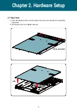
 Push the release button on both sides of the top cover and push it toward the 

     rear panel.


Lift the top cover to complete removal.

Chapter 2� Hardware Setup

2�1 Top Cover

Press and push.

Lift.

Summary of Contents for RSC-1AT

Page 1: ...UM_RSC 1AT_v1 1_062719 RSC 1AT Rackmount Storage Chassis User s Manual...

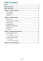
Page 2: ...dware Setup 5 2 1 Top Cover 5 2 2 Power Supply Unit Module 6 2 3 Fan Module 6 2 4 Hard Disk Drive 7 2 5 HDD Backplane Module 8 2 6 Riser Card 8 2 7 Slide Rail 9 Chapter 3 Hardware Specifications 13 3...

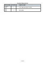
Page 3: ...Document Release History Release Date Version Update Content October 2018 1 User s Manual release to public June 2019 1 1 QIG update Content...

Page 4: ...Copyright 2018 AIC Inc All Rights Reserved This document contains proprietary information about AIC products and is not to be disclosed or used except in accordance with applicable agreements...

Page 5: ...is essential that only the supplied power cord be used 2 Use only shielded cables to connect I O devices to this equipment 3 You are cautioned that changes or modifications not expressly approved by t...

Page 6: ...from humidity Carefully mount the equipment into the rack in such manner that it won t be hazardous due to uneven mechanical loading This equipment is to be installed for operation in an environment...

Page 7: ...equipment does not work well or will not work according to its user manual 5 The equipment has been dropped and or damaged 6 The equipment has obvious signs of breakage 7 Please disconnect this equipm...

Page 8: ...rall layout of the product including the fundamental components of the rackmount chassis design specifications and noteworthy features Chapter 2 Hardware Setup This chapter displays an easy installati...

Page 9: ...shipping carton may indicate that the contents of the carton are damaged If any damage is found do not remove the components contact the dealer where the subsystem was purchased for further instructio...

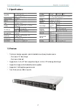
Page 10: ...Cooling Middle 4 x 40x56mm PWM 1 x 40x28mm hot swap fans Power Supply Standard 500W single PSU Option 650W 1 1 redundant Expansion Slot 1 full height Front Panel System power on off and system reset 2...

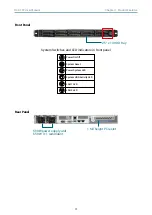
Page 11: ...l Front Panel System Switches and LED indicators in front panel Rear Panel 2 5 x 10 HDD tray 500W power supply unit 650 W 1 1 redundant 1 full height PCIe slot Power On Off System Reset System HDD Act...

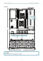
Page 12: ...ter 1 Product Features RSC 1AT User Manual Top View NOTE Motherboard is not included in this product 1x 4028 hotswap fans 4 x4056 PWM fans 500W single power supply unit 650W 1 1 redundant power supply...

Page 13: ...are Setup RSC 1AT User Manual Push the release button on both sides of the top cover and push it toward the rear panel Lift the top cover to complete removal Chapter 2 Hardware Setup 2 1 Top Cover Pre...

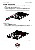
Page 14: ...y pushing it into the chassis Ensure that the module is accurately inserted and locked into the chassis 2 2 Power Supply Unit Module Unplug the cables and connectors Lift the fan module upward Check t...

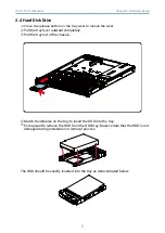
Page 15: ...utward completely Pull the tray out of the chassis Match the dimples on the tray to insert the HDD into the tray Pull upward to remove the HDD from the HDD tray Make certain that the HDD is not damage...

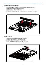
Page 16: ...riser card braket Install the braket with the PCIe card into the chassis Detach the cables and hard disk drives from the backplane module Release the module by shifting the hook Dislodge the screws o...

Page 17: ...per order The rail in this manaul may not exactly match the rail for your system Please refer to the spefications or quick installation guide that came with your purchased product 1 Pull on the Front...

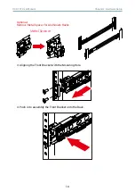
Page 18: ...er 2 Hardware Setup RSC 1AT User Manual Optional Remove Metal Spacer for Aluminium Racks 3 Aligning the Front Bracket with the Mounting Hole 4 Push in to assembly the Front Bracket onto the Rack Metal...

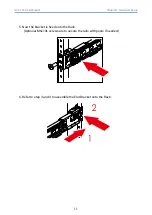
Page 19: ...2 Hardware Setup RSC 1AT User Manual 5 Now the bracket is fixed onto the Rack Optional M6x10L screws are to secure the rails with posts if needed 6 Refer to step 3 and 4 to assemble the End Bracket on...

Page 20: ...12 Chapter 2 Hardware Setup RSC 1AT User Manual 7 Assemble the inner channel onto the chassis using thescrews provided 8 Push the chassis with inner channels into Slide to complete Rack Installation...

Page 21: ...cification RSC 1AT User Manual 3 1 HDD Backplane 2 Bay 3 1 1 Layout Top view Bottom view This chapter illustrates a detailed instruction guide on hardware specifications HDD Connect SATA Port Chapter...

Page 22: ...hapter 3 Hardware Specification RSC 1AT User Manual 3 1 2 Connector and Jumper Bottom view J7 JP1 J3 JP1 J3 J7 Power JP1 12V GND GND 5V LED I O J3 J7 Fail LED LED ACC LED Fail LED input GND ACC LED in...

Page 23: ...15 Chapter 3 Hardware Specification RSC 1AT User Manual 3 2 1 Layout Top view Bottom view 3 2 HDD Backplane 4 Bay SFF 8643 Connector SFF 8643 Connector...

Page 24: ...r JCPLD_SEL SGPIO Function and Setting Pin Status Description 1 2 Open Disable External Access LED input JP11 Close Enable External Access LED input JP11 3 4 Open Access LED from HDD Pin P11 Close Acc...

Page 25: ...aicipc com tw North California United States Address 48531 Warm Springs Boulvard Suite 404 Fremont CA 94539 United States Tel 1 510 573 6730 Fax 1 510 573 6729 Sales Email sales aicipc com Support Em...

Reviews: