background image

9

Chapter 2. Hardware Setup

2�5 Slide Rail Installation

NOTE

This sections provides a basic instruction for mounting the slide rail onto the system. 

Tool-less rails vary per order. The rail in this manaul may not exactly match the rail for 

your system. Please refer to the spefications or quick installation guide that came with 

your purchased product.   

CAUTION

The rack may tilt and fall due to incorrect installation or placed on uneven grounds. The 

rack must be placed in a flat surface before you begin to slide the system barebone in 

for servicing.

 Pull the inner rail out of the slide rail.  

 Detach the inner rail completely from the slide rail by pulling the white tab foreward.

detached inner rail

inner rail

tab

Summary of Contents for RMC-1E

Page 1: ...UM_RMC 1E_v1 1_032421 RMC 1E Rackmount Chassis User s Manual...

Page 2: ...bout This Manual iv Chapter 1 Product Features 1 1 1 Components 1 1 2 Specifications 2 1 3 Feature 2 Chapter 2 Hardware Setup 5 2 1 Top Cover 5 2 2 Fan Module 6 2 3 Hard Disk Drive 7 2 4 Riser Card 8...

Page 3: ...Document Release History Release Date Version Update Content February 2021 1 User s Manual release to public March 2021 1 1 Specifications update Content...

Page 4: ...Copyright 2021 AIC Inc All Rights Reserved This document contains proprietary information about AIC products and is not to be disclosed or used except in accordance with applicable agreements...

Page 5: ...is essential that only the supplied power cord be used 2 Use only shielded cables to connect I O devices to this equipment 3 You are cautioned that changes or modifications not expressly approved by t...

Page 6: ...ghly sensitive to static electricity Before operating a board or integrated circuit touch an unpainted portion of the system unit chassis for a couple of seconds to discharge any static electricity on...

Page 7: ...ty They must have a dummy cover Never open the equipment without professional assistence For safety reasons only qualified service personnel should open the equipment If one of the following situation...

Page 8: ...www aicipc com en productdetail 64 Chapter 1 Product Features This chapter delivers the overall layout of the product including the fundamental components of the rackmount chassis design specificatio...

Page 9: ...continuing first unpack the subsystem and verify that the number of components in the shipping carton is accurate and in good condition 1 1 Components This product contains the components listed below...

Page 10: ...led steel Color Front Panel Black Cooling Standard 3 x 40x28mm fans Power Supply Standard 250W single PSU Expansion Slot 1 full height via riser card Front Panel LED Indicators Power LED HDD LED LAN 1...

Page 11: ...ve activity LED LAN1 LAN2 LED System BMC Alert System reset button 2 x USB port Rear Panel Item Content Description 1 PSU socket 250W single PSU 300W 1 1 redundant PSU BTO 2 LAN port 1 GbE RJ45 dedica...

Page 12: ...4 Chapter 1 Product Features Top View NOTE Motherboard is not included in this product 3 5 inch HDD 3 5 inch HDD 3 x 40x28mm fans...

Page 13: ...5 Dislodge screw on the top cover Push the cover towards the rear panel Lift upward to remove Chapter 2 Hardware Setup 2 1 Top Cover...

Page 14: ...fan module by dislodging the screw on the fan bracket Lift the fan module upward Check to carefully dislodge the rubber connectors from the attached bracket Insert the replaced fan into the chassis V...

Page 15: ...7 Chapter 2 Hardware Setup Lift the disk drive out of the chassis Insert the new disk drive into chassis Ensure that the dimples are accurately matched before installing the drive 2 3 Hard Disk Drive...

Page 16: ...8 Chapter 2 Hardware Setup Loosen the captive screw Lift the riser card bracket from the chassis 2 4 Riser Card...

Page 17: ...refer to the spefications or quick installation guide that came with your purchased product CAUTION The rack may tilt and fall due to incorrect installation or placed on uneven grounds The rack must...

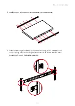
Page 18: ...onto the system barebone Lock the keyholes Continue installing the outer rail bracket to the mounting frame Attach the outer rail assembling to the frame and press the bracket to fix the rail onto th...

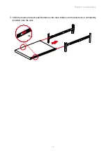
Page 19: ...11 Chapter 2 Hardware Setup Slide the release tab and push barebone into rack Make sure the barebone is completely installed onto the rack tab...

Page 20: ...ma russia aicipc com tw North California United States Address 48531 Warm Springs Boulvard Suite 404 Fremont CA 94539 United States Tel 1 510 573 6730 Sales Email sales aicipc com Support Email suppor...

Reviews: