S150/S151/S152/Z152
7-6
7
Rescue, Towing,
Lashing, Crane-Lifting
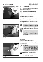
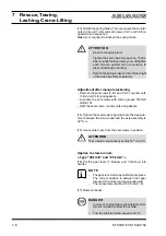
(13) Detach the spring brake. To do so, loosen the counter
nuts (7-4/2 and 7-4/4) and set screws (7-4/1 and 7-4/3) a
quarter turn in sequence.
One
turn is required to slacken the spring brake.
ATTENTION
-
Do not exceed one turn!
-
Tighten the set screws in sequence. That is,
when you tighten the screws, you must tighten
each screw a quarter turn in sequence to
prevent jamming or canting.
-
Detach the spring brakes to the left and right
of the axle assembly separately.
Adjustment after manual slackening
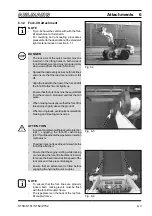
- Remove the set screws (7-4/1 and 7-4/3), counter nuts
(7-4/2 and 7-4/4) and gaskets.
- Lubricate the set screws with silicon grease TECNO
LUBE 101.
- Refit the set screws, counter nuts and gaskets.
(14) Tighten the set screws to a point where the measure-
ment between the screw head and the axle assembly is
32
+1
mm.
(15) Use counter nuts to fix the set screws in position.
ATTENTION
The screws must protrude by exactly 32
+1
mm (7-4).
Applies to slow-runners
» Type "20 km/h" and "25 km/h" «
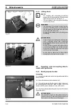
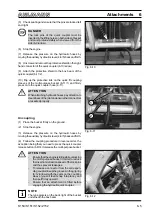
(16) Put the gear lever (7-5/arrow and 7-6/arrow) into
neutral.
NOTE
-
The gear lever will snap noticably into place.
The correct position is between first gear
(pressed in) and second gear (pulled out).
-
The measurement will be 123,5 mm (7-6).
(17) Remove chocks.
DANGER
-
In case of engine failure considerably more
force is required to steer the vehicle.
-
Tow the vehicle at slow speed (2 km/h).
i
Summary of Contents for AS 150
Page 7: ...Safety regulations ...
Page 19: ...Signs ...
Page 22: ...Anti TheftProtection ...
Page 25: ...Description ...
Page 34: ...Operations ...
Page 46: ...Attachments ...
Page 54: ...Rescue Towing Lashing Crane Lifting ...
Page 61: ...Maintenance ...
Page 80: ...Troubleshooting ...
Page 83: ...Wiring and Hydraulics ...
Page 98: ...Technical Data Equipment ...
Page 103: ...Technical Data Attachments ...
Page 112: ...Optional Extras Changes ...


