TOWARDS
DOOR EDGE
BOTTOM
TOP
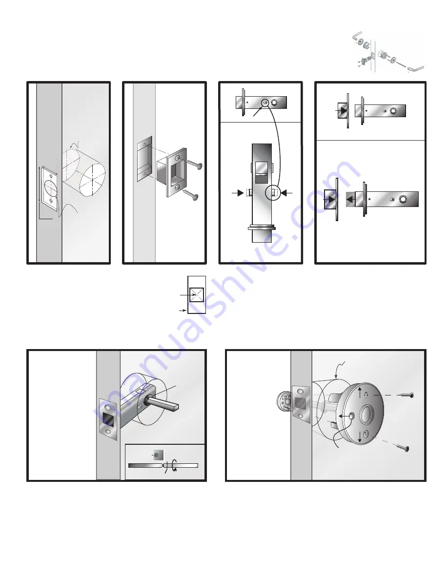
FIGURE 1
Drill 2 1/8” hole at correct
backset using included
template
FIGURE 3
FIGURE 2
Prepare frame for strike.
AHI HARDWARE
7548 Cote de Liesse St-Laurent,
Qc H4T 1E7, Canada
Tel. 514 335-8281
Tel. 877-339-8281
www.ahi-arch.com
1
2
To install the mag latch into
the door, make sure that the
privacy lock switch in
centered and that the
threaded side (see fig 4) is
facing the interior
FIGURE 4
1.
1.
ø
2 1⁄8”
2 ¼”
ø
1”
1”
In order to center the lock switch, the
latch must be extended. To achieve this,
place the latch near the strike box
FIGURE 6
Insert the sub rose into the 2 1/8” hole respecting the above orientation
Place the levers onto the spindle but do not tighten the lever set screw
Use the supplied screws (choose correct size based on door trim) and tighten
into sub rose assembly
Remove the levers
2 1/8” PRE-BORED HOLE
1.
2.
3.
FIGURE 5
Before installing the spindle, unscrew it 2 turns from the fully
tightened position, if the provided spindle does not have a center
screw, skip to figure 6
NOTE: The spindle must be inserted into the latch such that the stopper
disc rests against the latch on the interior side of the door, and that the
thin wall side of the spindle will align with the levers’ set screws
1.
2.
INTERIOR
EXTERIOR
INTERIOR
EXTERIOR
STOPPER DISC
STOPPER DISC
THIN WALL SIDE
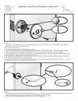
Magnetic Latch Privacy Installation Instructions
lock switch
1“ X 2 ¼”
23⁄32“ X 13⁄16”


