78
Installation and Verification Manual
3
Performance Tests
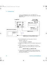
CLOCK to EXTERNAL 10 MHz REF
TERMINATION to 75 ohm UNBAL
LINE CODE to HDB3
PAYLOAD TYPE to UNFRAMED
PATTERN to 2^23 PRBS
15
Check that the Test Set CLOCK LOSS Alarm LED is not lit.
16
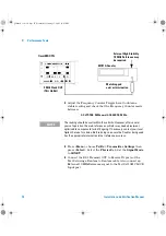
Adjust the Frequency Counter Trigger Level to obtain a
stable reading and check that the Frequency Counter reads
between:
2.047999999 MHz and 2.048000001
MHz
17
Confirm that the OmniBER OTN is locked to the External
signal by disconnecting/re-connecting the BNC cable at the
OmniBER OTN CLOCK IN port.
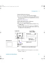
(External 2M Balanced Data as Reference)
18
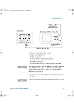
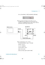
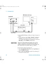
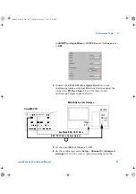
Change the set-up as follows. Disconnect and remove the Test
Set to OmniBER OTN (BNC to BNC) signal connection.
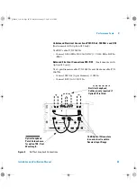
Connect a Balanced 3 pin Siemens cable between the Test Set
Data OUT 3-pin port and OmniBER OTN CLOCK IN 3-pin
port.
19
Change the Test Set Transmit TERMINATION to 120 ohm
BALANCED.
20
Check that the Test Set CLOCK LOSS Alarm Led is not lit.
21
Adjust the Frequency Counter Trigger Level to obtain a
stable reading and check that the Frequency Counter reads
between.
2.047999999 MHz and 2.048000001
MHz
22
Confirm that the OmniBER OTN is locked to the External
signal by disconnecting/re-connecting the BNC cable at the
OmniBER OTN CLOCK IN port.
(External DS1 Balanced Data as Reference)
23
Press
<Menu>
, choose
Tx/Rx > Transmitter Settings
then
press
<Select>
. Select the
Physical
tab. Set the
Signal Mode
to
SONET.
panther3_iv.book Page 78 Wednesday, January 15, 2003 12:03 PM

