Displaying Data
6
6000 Series Oscilloscope User’s Guide
287
•
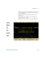
White traces show an idle bus (LIN 1.3 only).
•
Blue bi-level trace shows an active bus (inside a
packet/frame).
•
The hexadecimal ID and parity bits (if enabled) appear in
yellow. If a parity error is detected the hexadecimal ID and
parity bits (if enabled) appear in red.
•
Decoded hexadecimal data values appear in white and may
extend beyond the frame if an idle period follows.
•
For LIN 1.3, the checksum appears in blue if correct, or red if
incorrect. The checksum always appears in white for LIN 2.0.
•
Red dots in the decode line indicate that there is data that is
not being displayed. Scroll or expand the horizontal scale to
view the information.
•
Unknown bus values (undefined or error conditions) are
drawn in red.
•
If there is an error in the synch field, SYNC will appear in
red.
•
If the header exceeds the length specified in the standard,
THM will appear red.
•
If the total frame count exceeds the length specified in the
standard, TFM will appear red (LIN 1.3 only).
•
For LIN 1.3 a wakeup signal is indicated by WAKE in blue. If
the wakeup signal is not followed by a valid wakeup
delimiter a wakeup error is detected and displayed as WUP
in red.
Summary of Contents for InfiniiVision DSO6014L
Page 2: ...Agilent Technologies Agilent 6000 Series Oscilloscopes User s Guide...
Page 59: ...58 6000 Series Oscilloscope User s Guide 1 Getting Started...
Page 109: ...108 6000 Series Oscilloscope User s Guide 2 Front Panel Controls...
Page 125: ...124 6000 Series Oscilloscope User s Guide 3 Viewing and Measuring Digital Signals...
Page 251: ...250 6000 Series Oscilloscope User s Guide 5 Making Measurements...
Page 287: ...286 6000 Series Oscilloscope User s Guide 6 Displaying Data Interpreting Decoded LIN Data...
Page 321: ...320 6000 Series Oscilloscope User s Guide 7 Saving and Printing Data...
Page 370: ......


