208
Introduction to the Autosampler
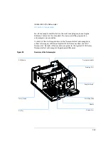
Sampling Unit
Needle-Drive
The needle movement is driven by a stepper motor connected to the
spindle assembly by a toothed belt. The circular motion of the motor is
converted to linear motion by the drive nut on the spindle assembly. The
upper and lower needle positions are detected by reflection sensors on the
sampling unit flex board, while the needle-in-vial position is determined
by counting the motor steps from the upper needle-sensor position.
Analytical head / preparative head
The analytical head is driven by the stepper motor connected to the drive
shaft by a toothed belt. The drive nut on the spindle converts the circular
movement of the spindle to linear motion. The drive nut pushes the
sapphire plunger against the tension of the spring into the analytical head.
The base of the plunger sits on the large bearing of the drive nut, which
ensures the plunger is always centered. A ceramic ring guides the
movement of the plunger in the analytical head. The home position of the
plunger is sensed by an infra-red sensor on the sampling unit flex board,
while the sample volume is determined by counting the number of steps
from the home position. The backward movement of the plunger (driven by
the spring) draws sample from the vial.
Table 42
Analytical Head Technical Data
Standard
(100
µl
Micro (40
µl)
Standard
(900
µl)
Preparative
(900
µl)
Number of steps
15000
60000
15000
15000
Volume resolution
7 nl/motor step
0.7 nl/motor step 60 nl/motor step 60 nl/motor step
Maximum stroke
100 µl
40
µl
900
µl
900
µl
Pressure limit
400 bars
400 bars
200 bars
400 bars
Plunger material
Sapphire
Sapphire
Sapphire
Sapphire
Summary of Contents for G1313A
Page 1: ...s1 Agilent 1100 Series Standard Micro and Preparative Autosamplers Reference Manual ...
Page 3: ...Reference Manual Agilent 1100 Series Standard Micro and Preparative Autosamplers ...
Page 12: ...12 Contents ...
Page 39: ...2 2 Optimizing Performance How to optimize the autosamplers to achieve best results ...
Page 93: ...93 Troubleshooting and Test Functions Step Commands ...
Page 216: ...216 Introduction to the Autosampler Electrical Connections ...
Page 244: ...244 Theory of Operation The Main Power Supply Assembly ...
Page 265: ...265 Introduction to the Control Module Diagnostics and Tests ...
Page 268: ...268 Introduction to the Control Module Diagnostics and Tests ...
Page 274: ...274 Specifications Performance Specifications ...
Page 275: ...10 Legal Safety and Warranty Information ...
Page 286: ...286 Agilent Technologies on Internet ...
Page 290: ...290 Index ...
Page 291: ......


