


132
N9912A FieldFox User’s Guide
How to select Zeroing
o
Press
Meas Setup 4
o
Then
Zero
o
Press
Zero Off
to turn zeroing off.
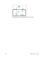
1-Port Cable Trimming Measurements
A 1-Port Cable Trimming measurement is used in a cable fabrication procedure
to validate proper electrical length. Read the
Overview
section in this chapter to
learn more about this measurement and the calibration process.
How to make a 1-Port Cable Trimming Measurement
Setup:
1. Press
Mode
then
VVM
then
1-Port Cable Trimming
.
2. Press
Freq/Dist
and enter the frequency needed for the VVM measurement.
3. Press
Meas Setup 4
then
Zero OFF
.
4. If using an adapter or jumper cable to connect the cables to the FieldFox,
press
Cal 5
then select
Calibration Type
,then either
QuickCal
(+ Load) or
OSL Cal
. Follow the FieldFox calibration prompts.
Verification:
Perform the following
optional steps
to ensure that the FieldFox is
properly calibrated. Steps 1 through 9 need only be done once to determine the
difference in phase between the Open and Short standard. Once that value is
known, perform steps 10 through 14 to verify a calibration.
1. Press
Mode
then
NA
. Select
S11
.
2. Press
Freq/Dist
and enter start and stop frequencies that span about 40% of
the VMM measurement frequency. For example, for a 1 GHz measurement,
enter Start .8 GHz and Stop 1.2 GHZ
3. Perform a calibration using a cal kit (NOT Quick Cal).
4. Press
Meas 1
then
Format Phase
5. Connect the Short standard to the RF OUT calibration plane.
6. Press
Trace 6
then
Math and Memory
then
Data -> Mem
7. Connect the Open standard to the RF OUT calibration plane.
8. Press
Data Math
then
Data/Mem
9. Press
Marker
then scroll the marker to the VVM frequency. The Y-axis value
is the phase difference in degrees between the Open standard and the Short
standard at that frequency.
Remember this value
!
10. Press
Mode
then
VVM
.
11. Connect the Short standard to the RF OUT calibration plane.
12. Press
Meas Setup 4
then press
Zero
13. Connect the Open standard to the RF OUT calibration plane.
14. Confirm that magnitude measurement is less than –0.1 dB and the phase is
within .1 degrees of the value from step 9.
Perform Cable Trimming:
Summary of Contents for FieldFox N9912A
Page 15: ...Preparing for Initial Use of Your New FieldFox 15 Take the FieldFox Tour Front Panel ...
Page 194: ...194 N9912A FieldFox User s Guide Batteries Safe Handling and Disposal ...
Page 195: ...Safety Considerations 195 Inspired Energy Battery ...
Page 196: ...196 N9912A FieldFox User s Guide ...
Page 197: ...Safety Considerations 197 ...
Page 198: ...198 N9912A FieldFox User s Guide ...


